effector tilting into bed on print
-
Looking at that video, I can see that the effector is tilting a lot. Also, at the first probe point the fan duct fouls the bed (because of the tilt) before the nozzle can contact it.
My first thought was that the spacing of the ball centres was not the same at the top and bottom of the pairs of rods. But if you are certain that it is the same, then I can think of another explanation. You have mounted the ball studs on the sides of the effector, not on the top as is usual. This may mean that the range of movement of the joints is insufficient. Those ball joints can go to nearly 90 degrees away from the aligned position, but I think more than 90 degrees is required if the studs on the effector are mounted horizontally. I suspect that the Delrin rod ends are fouling on the neck of the ball studs at some positions.
-
Good Catch David I never thought of that but it is more than Logical
-
I never considered the mounting of the balls. It certainly makes sense that it could be the problem. I had arrived at the conclusion that the rods must be the issue based on this machine printing very nicely before a couple of rods separated from their fish eye screw sockets.
I have no other option but a horizontal mount for the balls on the effector. To that end, I refurbished all of the rods / sockets and they are now secured with heat shrink tubing. I have replaced the magnetic rods with the originals and I am now working my way through the setup to reset the machine as a new install.
My latest tracking shows the Duet effector arriving on July 31. Until then, I will see what happens with the old rods. That should get us an environment that will confirm your suspicions.
Thanks so much for staying with me on this. -
I am content with the initial settings. The printer will cycle between home and z=0 realiably.
I have determined and saved the trigger height at 0.528. That does change a little on occasion, 0.515 seems to be the other number that pops up.
M500 has been issued.
I believe I am ready to run G32. Agreed?
-
G32 results
G32
Calibrated 6 factors using 10 points, deviation before 1.141 after 1.055
12:02:09
PMG32
Calibrated 6 factors using 10 points, deviation before 3.913 after 0.461Feedback? Possibility of printing?
I can watch the effector through the process and it is gliding like a flying saucer - base is flat.
-
You still have a large calibration deviation. What probing radius are you using? You could try reducing it until you get good calibration results, and then restrict your prints to that radius until you can sport out the effector.
-
@timvukman said in effector tilting into bed on print:
I never considered the mounting of the balls. It certainly makes sense that it could be the problem.
Just my "eyeball" from the vid, so take with a grain of salt: The rods look WAY too long for the other dimensions of the printer.
Curious, what are the rods (ball center to ball center), what are the horizontal extrusions (not counting the corners) and what are the vertical extrusions (again, not counting corners)?
And, if you know, what "brand" of corners?
-
This is looking much better. I took 10 out of the radius for now.
6:24:31 PMG32
Calibrated 6 factors using 10 points, deviation before 0.945 after 0.943
6:22:57 PMG32
Calibrated 6 factors using 10 points, deviation before 0.954 after 0.949
Look better? -
@timvukman said in effector tilting into bed on print:
This is looking much better. I took 10 out of the radius for now.
6:24:31 PMG32
Calibrated 6 factors using 10 points, deviation before 0.945 after 0.943
6:22:57 PMG32
Calibrated 6 factors using 10 points, deviation before 0.954 after 0.949
Look better?The deviation is consistent now (i.e. the "before" deviation reported by G32 is close to the predicted "after" deviation of the previous G32). However the absolute deviation is still very high, which will make printing difficult.
-
Not sure what else can be done unless I further reduce the radius. Not a big deal. I'm ok with printing small things. That's what I am trying to get done at the moment. Just a toothpaste squeezer for my step daughter.
This whole conversation does make me wonder or at least think I need to do something else going forward.
Once I get the new duet effector, I can of course mount the balls vertically for the magnetic rods. Is that combination likely to deliver an acceptable level of quality.
I have been giving serious consideration to replacing the plastic pieces that came with this printer with aluminum or some kind of metal. I would think metal parts would square up much better with the verticals that really are about the only metal that was in the kit. I have a feeling you would agree. Should I also expand the size of the verticals. Right now they are 20 x 20. I have seen the metal frame parts available with 20 x 40 openings for the verticals. Is that a worthwhile investment?
Thanks
Tim -
Took another 10mm out of the radius
7:10:42 PMG32
Calibrated 6 factors using 10 points, deviation before 0.911 after 0.910
7:08:56 PMG32
Calibrated 6 factors using 10 points, deviation before 0.924 after 0.919 -
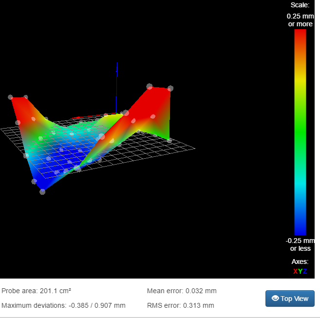
Something is very wrong if you can't get below 0.9mm deviation. If you run mesh bed levelling, with the same radius set as you are using for auto calibration, what does the height map look like?
What belts are you using?
Did you remember to change the L parameter in M665 to the length of the rods you are now using?
-
The belts are LL 2GT - 6. Perhaps they are not tight enough?

-
I was more concerned that the belts might be steel core, which are known to be unsuitable for delta printers.
The height map shows that there is something wrong with the mechanism. I suggest you work through the list of likely errors at https://duet3d.dozuki.com/Wiki/Calibrating_a_delta_printer#Section_Make_sure_your_build_is_accurate. One other test to do is to check that pure Z moves through the available height don't show any XY motion.
-
Yes, I did change the L parameter in M665.
I just got the mail, and my duet effector arrived. Thanks so much for including a spirit level in the kit. That was a nice surprise.
Obviously, I have much to take apart to install this kit. I promise I will work through each stage of the Make sure your build is accurate. I am seriously interested in seeing what I might find.
We'll see how long this takes and then I will report back.
-
The new effector is installed with the magnetic rods.
HomeDelta worked fine. I have lights! I hate all crimp connectors!!!
Putting the carriage adapters in took a little creativity. I have three wheels on each, staggered, and the length of one screw was preventing the backing plate from sitting properly. A shorter screw solved the problem, so all is good. All three are identical in construction and are at the same level when homed.
I have no housing for the part fan until I print one, so we shall see how that works at some point down the road.
I also have lost my trigger height capability since it was a physical switch triggered mechanically on the old effector.
On to setting Z=0
-
I'm curious since I have no Z probe right now.
"Your can run auto calibration without a Z probe if you tell RepRapFirmware that you have no Z probe, by using parameter P0 in your M558 command in config.g. However, auto calibration is easier and faster if you have a Z probe. The choice of a suitable Z probe should take account of the following factors:"
The above text was in the page you pointed in your text.If I were to manually send the effector down to z0 at various places, would that give me an accurate reading at each point? ie, since I can't run G32 without a Z probe. (I am assuming that I can't run G32 since I have no spring / switch assembly to protect the nozzle.
Could I run G32 is I set the dive height to 0?
-
I thought you bought the Smart Effector? It has the Z-probe built in.
-
This is the description
The Smart Effector for delta printers allows the hotend to be used as a Z probe giving fantastic accuracy across the whole delta build area by eliminating the effect of tilt. It uses precision PCB manufacturing to ensure equal hole spacing between the effector and the carriages on the towers, further improving accuracy.
Supplied with a custom machined e3d v6 heatsink (produced by e3d on our behalf).
Supplied with 3 PCB carriage adapters with 20mm mounting hole spacing compatible with common linear rails and wheel carriages.
Compatible with Haydn Huntley’s Magball delta arms - available from Haydn directly or other suppliers.
The smart effector simplifies wiring of hotend components with plug connectors from thermistor and fans along with a screw terminal for the heater cartridge. Molex and microfit connections are then used for wiring looms back to the control electronics. Crimp pins and housings are supplied for all connections
On board LEDs for print illumination are compatible with either 12V or 24V power supplies with a jumper selecting the voltage.
More detail is available on the wiki.We recommend you purchase directly from Think3DPrint3D if you are located in the UK.
What's in the box:
Smart Effector board
3 x PCB carriage adapters
Custom E3D heatsink
Connector kit
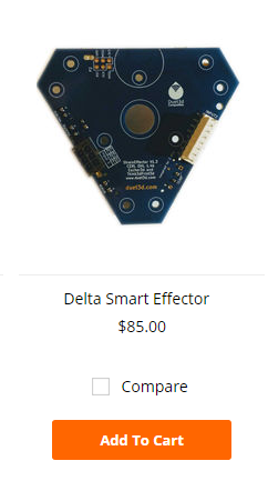
Buy a Smart Effector from #Spool3D for your 3D printer in Canada without the surprise cost of the exchange rate!This is the photo

I see nothing on the board that indicates there is a z probe installed. I have one on my other printer, which is a separate item. I was assuming it is built in somehow on this board. I see where the cable connects on the 8 pin connector, but there are no angled leds on the board like there are on the separate unit I have.
There is nothing on the hot end that extends close enough that it would trigger. Should there not have been a separate board included? It looks like it is supposed to be screwed onto the fan bracket according to the documentation, but I have no separate board.
-
My kit did not have the blue cap shown covering the nozzle. Is that where the probe is?