Driver Error and MCU overheating
-
@TobiAsis what temperature is very high? 45-50 degrees is the standard running temp for the MCU on these boards
what overheat error are you actually seeing?short to ground is normally an issue with wiring
-
@jay_s_uk Thanks!
This is the MCU temperature. I assumed it would be too high, because I had an error, something like "Overheat error", around the 50C and it shut off. Unfortunately, I am not able to replicate it and I do not remember the precise wording.
However, I feel like at around 50C, it randomly reboots or re-runs the config.g (I can tell, because i have a homeall sequence there, and I hear some sound and then the homing sequence starts off. It is all quite mysterious). This is why I thought, it went into overheat error, and then rebooted itself.I am using a Mini 5 + btw, which according to a document on the duet docs (I cannot post the link because i need " two reputations") might have trouble with temperature readings. I was not able to view the temperature of the motor controllers.
Wiring issue means that the wires itself are somehow broken? I can be sure that the pins are definetly correct.
-
I just tried to only spin the x-axis again and this happened immediately:
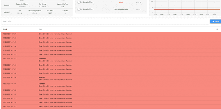
The only thing I can do is emergency stop, so I can even access anything behind all these error messages. The MCU temp is now 54C. The Duet was idling for about half an hour now. The Stepper driver temp is either 0 or 100C
Driver or MCU do not feel very hot, I can touch them with my hands, I would say maybe 30-40C
-
@TobiAsis Are you able to post details of the IGUS stepper motors?
-
@gloomyandy it should be this model https://www.igus.de/product/MOT-AN-S-060-002-042-L-A-AAAO
-
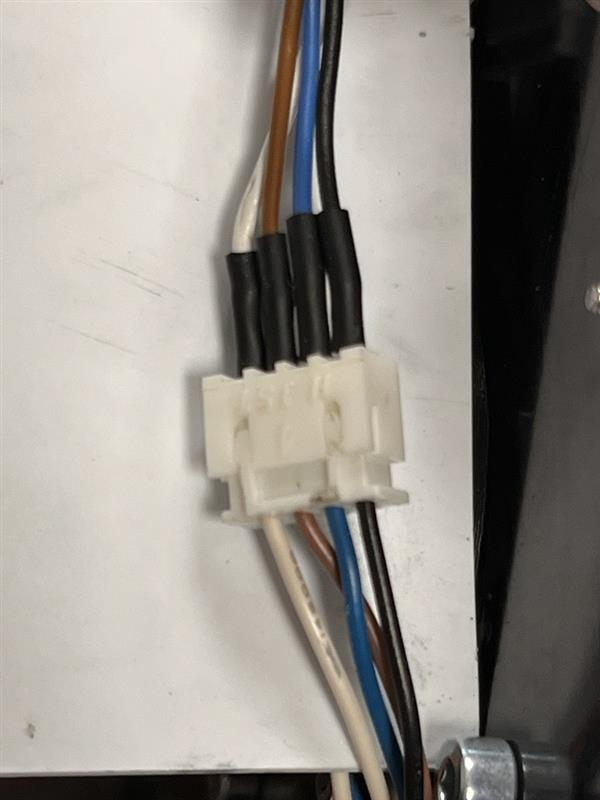
@TobiAsis can you post photos of your wiring at the duet 3 mini side?
Owns various duet boards and is the main wiki maintainer for the Teamgloomy LPC/STM32 port of RRF. Assume I'm running whatever the latest beta/stable build is
-
Perhaps I found something interesting.
I turned the board off and let it cool down a bit. The MCU temperature was very low again. Upon turning on and homing everything, I ran a macro which spins my 0.0 stepper really slowly. To monitor the current, it placed my multimeter on the power in. What surprised me is that I saw a current draw of 1.4A, even with the motor spinning super slowly (F100). After just few seconds, I immediately go the driver overheat error again.
I then changed the speed to F500, ran it again and the current was just about 250mA. Now, I did not observe the overheating error.The question would now be: Why does it draw so much current when spinning very slowly? Is it a microstepping thing?
Also, the board is advertised with 1.4A, peak 2A. I am surprised that it already shuts off at 1.4A then.
-
-
@TobiAsis how do those colours on the motors correspond to the colours on the cabling they're supplied with?
-
@jay_s_uk I wired the colors to be exactly the same
-
@TobiAsis Did you study the Mini 5+ Hardware Overview?
In the section Cooling it states:
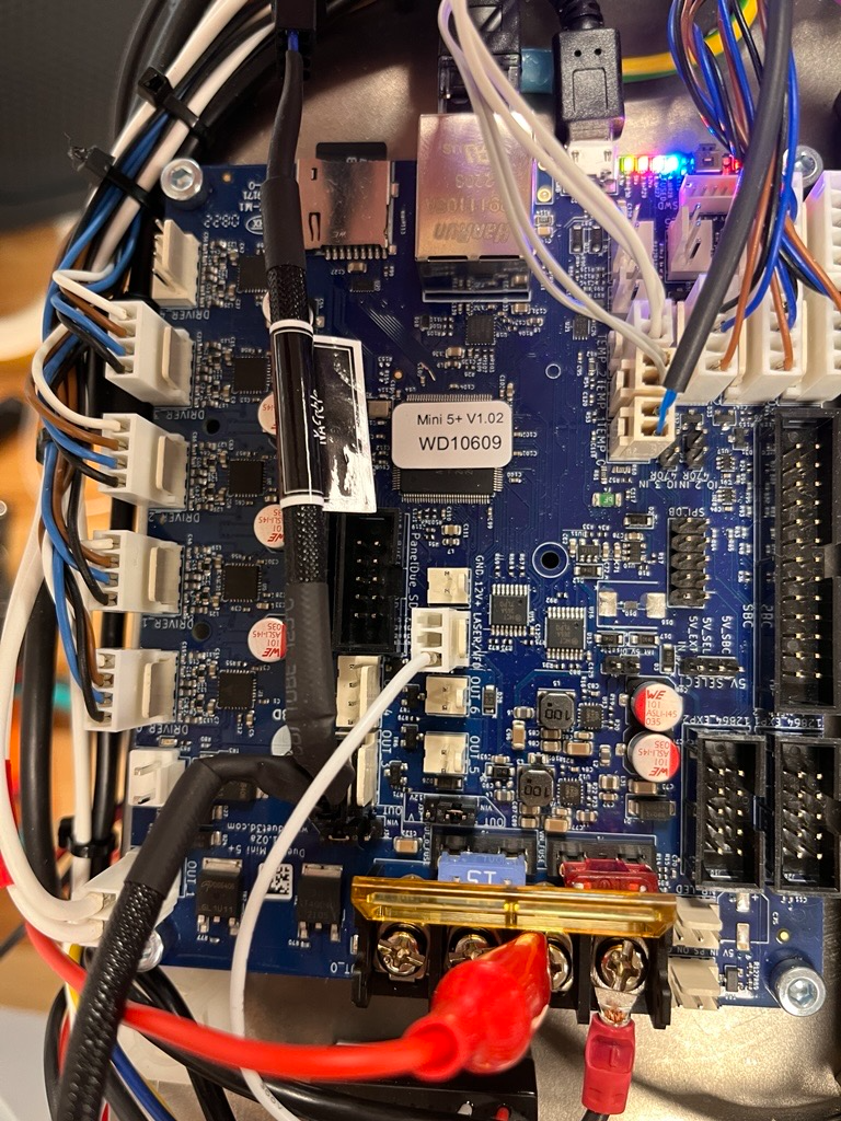
In many applications passive cooling will be sufficient, especially if the board is mounted vertically in a well ventilated position. If active cooling is needed then a fan blowing across the back of the board along the line of the stepper drivers is recommended.
The stepper drivers' heatsinks are connected to the PCB and the majority of the heat is dissipated via the PCB so heatsinks on the stepper driver chips are largely ineffective.
Looking at your photo, I doubt that much heat can be dissipated from the PCB’s back. Better ventilation or active cooling may be required.
To the temperature readings you get: The two subsequent paragraphs in the above mentioned doc (”MCU Temp” and ”Stepper Driver Temp”) explain why RRF reports strange values.
-
@TobiAsis Usually stepper motors are rated at either 'peak' or 'RMS' current, unfortunately Igus have chosen to rate theirs at the 'nominal' current of 1.4A. I'm not sure what this means! I'd tend to assume this is their peak current, and you should run them at a maximum of 80% of that current, ie 1100mA. Running at peak current will heat up the motor, and possibly cause the other issues you were seeing with phase shorts.
Looking at the specification https://www.igus.eu/product/MOT-AN-S-060-002-042-L-A-AAAO?artnr=MOT-AN-S-060-002-042-L-A-AAAO these motors are 30.5mm long, with an inductance of 2mH, which is not high. I would think you don't need to run these with a high current.
For cooling see https://docs.duet3d.com/Duet3D_hardware/Duet_3_family/Duet_3_Mini_5+_Hardware_Overview#cooling
We don't recommend a specific current limit before cooling is required, because it depends on the application.Also note that full current is always drawn by the stepper driver, even if the motor is stationary. A stationary motor can heat up just as much, or even more, than a moving motor, as there's no movement to encourage air circulation. The stepper driver varies the voltage, not the current. The M906 I and T parameters only come into affect when the machine is idle, ie no motors moving.
For a deep dive into motors and RepRapFirmware, see https://docs.duet3d.com/en/User_manual/Connecting_hardware/Motors_choosing
Ian
-
@TobiAsis your config.g file shown that you are running the drivers in stealthChop mode. It's a feature of the TMC2209 and other drivers that stealthChop mode doesn't work properly at high speeds and can lead to excessive currents and resulting errors. So we advise only using stealthChop mode at very low speeds. There is a M569 parameter that lets you set the changeover speed.
-
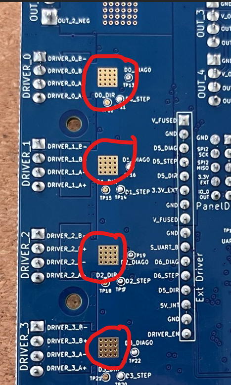
@infiniteloop Thanks for the hint! Indeed I was not aware of this. You are right that the PCB is mounted in a way that there is very much restricted airflow in the back. I will make some design changes to allow some airflow in the back there. Do I understand correctly that essentially these areas are the heat dissipation zones?
@droftarts This is interesting. You mentioned that always full current is drawn when a motor is running. This sounds like, if I set the current to, lets say, 1A, and I run the motor at various speeds, it should always draw 1A until it goes into idle? I have noticed that the current draw is often significantly lower than what I have set.
I had some previous issues with a motor stalling, and when I measured, I realized that the current draw was only about half of the current I specified in config. I experimented with increasing the current, and I only reached a full current draw when I set it to 2x the rated peak current of the motor.
Is there any relationship between current draw, load, speed or microstepping? What could be the explanation to this?@dc42 Thanks. How would you define low speeds and high speeds? I see values between 100 and 4000 in the M569 description, but there is no unit. I had made the observation that there was excessive current draw at very LOW speeds, and that it normalized with higher speeds.
-
@TobiAsis said in Driver Error and MCU overheating:
Do I understand correctly that essentially these areas are the heat dissipation zones?
Heat dissipation occurs over a much larger area, but the marked spots are of central importance for this to work: The holes are copper-coated and transport the heat vertically through the multilayer circuit board.
-
@TobiAsis said in Driver Error and MCU overheating:
You mentioned that always full current is drawn when a motor is running.
Is there any relationship between current draw, load, speed or microstepping? What could be the explanation to this?Sorry, that's not entirely accurate, particularly as microstepping is generally used. It is accurate if you were using full stepping; at each full step, one (of the two) motor phases is at full current. However, with microstepping, between one full step of the stepper motor and the next, the voltage for a single phase varies in a sine wave from 100% to -100% and back to 100% (a transistor switches the voltage direction to reverse the polarity of the coil for the 'negative' part of the sine wave, switching magnetic direction of the coil). The voltage required for each step is set by V=I x R, where R is the coil resistance. So the current is varied to achieve the voltage required for that step, up to the maximum current limit. The stepper drivers are called 'constant current chopper drivers' because the input voltage (ie 24V) is 'chopped' (ie turned on and off very fast) to produce an averaged output voltage (for the motor coil, usually only a couple of volts), using the current as a reference, so the current remains 'constant' at that particular microstep.
Because of this, while the (maximum) current may be set to 1100mA, most of the time the stepper driver won't be drawing that much current, and averaged out over time will be drawing considerably less. Which is why the 10A fuse on V_FUSED is capable of supplying sufficient current for the 12V Regulator, 5V regulator, Stepper drivers (including external driver header), OUT 1 and OUT 2 headers, V_OUTLC1 and V_OUTLC2 selection jumpers.
Load generally doesn't matter; either the motor has the torque to overcome the load, or it doesn't and will skip steps. Speed is different, as torque reduces with speed, and there are various other complications such as back EMF, but that would require a much more complex answer, and I'm not an electrical engineer!
(Note: the above is my understanding of how a stepper driver works. I'm happy to be corrected.)
I had some previous issues with a motor stalling, and when I measured, I realized that the current draw was only about half of the current I specified in config. I experimented with increasing the current, and I only reached a full current draw when I set it to 2x the rated peak current of the motor.
I think the problem is how you're measuring the current. How are you doing that? If you're using an oscilloscope, you could see the current changing, depending on where you are measuring. If you're using a multimeter, you're probably seeing the average current over time, ie half the current. If the motor is stationary, it will depend on where in the step it is stopped.
Setting the current to double the recommended motor current is going to overheat the stepper motor and burn out the wiring, and cause a phase short error message. It may also damage the stepper driver. Don't do it!
Ian