Speed affects extrusion rate with pellet extruder
-
@p8blr you probably want to look at non linear extrusion and calibrate that
-
-
@droftarts Can you explain or link me to an explanation of this equation: (1 + min(L, Av + Bv^2)) ?
I read through the forum posts linked in the M592 description but I still don't understand the theory behind that equation, let alone how to determine the A and B coefficents.
Thanks.
-
@p8blr the A and B coefficients are those of a parabola that best fits the extrusion multiplier vs. speed curve. I suggest you establish the required extrusion multiplier at lower speeds so that you can determine a base extrusion multiplier at low speeds.
Alternatively you could command the extruder to extrude a fixed amount of plastic at various speeds, then weigh the amount extruded at each speed to determine how the amount of extrusion decreases with speed and hence what multiplier is needed.
-
@dc42 I collected some data, but I'm not sure how to make an equation that fits the format. I can't set an intercept of 1. Was my mistake that I calibrated at my maximum speed?

I'm racking my brain trying to figure out how to make an equation that doesn't have a constant and I can't figure it out.
Marlin supports a constant:

-
@p8blr if you think you need a constant then your extruder steps/mm is set incorrectly. It should be set so that you need an extrusion factor of 1 at low speeds.
-
@dc42 the steps/mm are correct. I have them set to the values specified by the extruder manufacturer.
Does this make more sense?
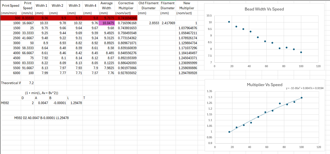
- Print same part multiple times, only varying the print speed. (Two perimeter thick print, no infill)
- Measured the wall thickness several times, average them.
- Omit the 500mm/min speed because it is an outlier (may be a limitation of the pellet extruder)
- Theoretical bead width is 3.6mm, I take the nominal value (2*3.6mm) and divide it by the actual widths. This gives me an extrusion multiplier - I refer to it as the "corrective multiplier".
- Because I'm not using filament, my slicer has an arbitrary "filament diameter", I use the extrusion multiplier to recalculate a new filament diameter (Surface area * coefficient = surface area, solve for Diameter)
- I now create a new extrusion multiplier, based on the new extrusion multiplier at 1000mm/min being 1. This is calculated by taking the new nominal width, divided by the actual widths.
- I plot the extrusion multiplier vs the extrusion speed in mm/s (as specified in the M592 documentation) and apply a 2nd order polynomial trendline.
I end up with these coefficients:
M592 D2 A0.0047 B-0.00001 L1.29478What is strange is that when I apply these, sometimes my extruder doesn't extrude at all.
Please let me know what you think. Thank you.
-
@p8blr just a note that for whatever reason the Marlin implementation opted to swap the A and B parameter meaning. Maybe looking at Marlin docs caused a mix up?
-
@p8blr looks like your factor vs speed plot is linear, so you can omit the B parameter entirely. Change the extruder steps/mm so that plot crosses extrusion factor 1 at speed 0.
-
This post is deleted! -
@dc42 How exactly do I modify the esteps/mm so that the plot crosses extrusion factor 1 at speed 0? I'm getting better results using a linear trendline, however, the issue I keep running into is this:
If I calibrate my esteps/mm at the slowest speed I use (1000mm/min for instance), then print some test prints at faster speeds, measure the widths, plot the results, my extrusion multiplier will always be off on the speed I calibrated at, i.e. if A = 0.0036, and I calibrated my multiplier to be 1 at 1000mm/min then my multiplier is now 1.0036 now at 1000mm/min.
-
@p8blr in that example you would divide your E steps/mm by 1.0036.
The best fit line in the graph in your earlier post showed an intercept of 0.9194 so if using that to provide the parameters you would multiply the steps/mm by 0.9194.
-
 undefined p8blr referenced this topic
