LIS3D using SPI issues
-
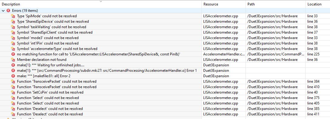
@dc42 I updated the LISAccelerometer.cpp and now getting the following errors:
-
@wayneosdias if in file EXP1HCL.h I change the value of
# define SUPPORT_I2C_SENSORSfrom 1 to 0 then I get just one compilation error, not the ones you report. I suspect you may have changed the definition ofSUPPORT_SPI_SENORSfrom 1 to 0 because that would disabled the shared SPI code, leading to those compilation errors.I have committed a fix for the compilation error that I saw. Note, SPI-connected accelerometers on expansion boards have never been tested so there may be further issues with the code.
-
@dc42
Hi David, I didn't change the #define SUPPORT_SPI_SENSORS 1, but I did change quite a bit of the file. For the sake of completeness I attached my full config file. I've tried being very explicit of my flagging changes by prefacing changes, eg;//**REMAPP**//constexpr size_t MaxPortsPerHeater = 1; /**REMAPPED**/constexpr size_t MaxPortsPerHeater = 0;I don't expect you to comb thru my full config, but if you do take a look and see anything off it'd be great if you let me know

Meantime Ill revert the LIS3DH back to I2. I only made that change as I prefer SPI to I2C. But if SPI is causing probs and hasnt been tested then Ill go back I2C.
Thanks again
-
@wayneosdias
Unwinding my SPI and I2C changes I see a change that I didn't make that I should have://**REMAPP**//# define ACCELEROMETER_USES_SPI (0) // accelerometer is connected via SPI /**REMAPPED**/# define ACCELEROMETER_USES_SPI (1) // accelerometer is connected via SPII tried that but still errors. I still plan to unwind everything and go back to I2C
-
@dc42
SPI success! Before unwinding everything, I took another look at the git repo and spotted LISAccelerometer.cpp had been updated after my other file update. I updated that file and everything compiles for LIS3D on SPI.Ill mark this question as solved once I confirm HW function. I have the chip carrier for the SAME5 on order but probably won't rec for a couple weeks. I may just order the PCB regardless as I need the machine back up and running and the accelerometer no critical for its fxn.
-
@dc42
I got the custom main FW running on the custom PCB and Looks like the lis3d chip is chatting w the mcu via spi. How do I bench test the lis3 functioning? I briefly tried the DWC input shaper plugin, but it complains about the machine not being homed. There are no kinematics/limits hooked up at the moment I just want to confirm on the bench the HW/FW are really working. How do I go about this?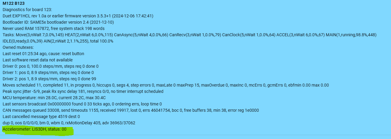
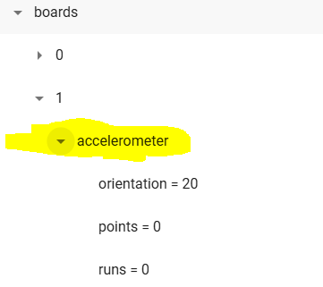
Thanks for any help guys
-
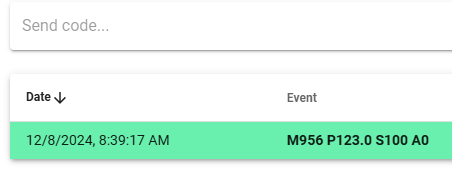
@wayneosdias you can use M955 to configure the accelerometer orientation and M956 to take readings.
-
@wayneosdias you can set axes to homed with G92 as well
-
@wayneosdias Once you have a set of readings (saved to a file) you can open that file to check the data. You would normally expect to see X and Y reading around 0 and Z reading around 1 (assuming you have the orientation set correctly and the board is level).
-
@dc42
hmm doesn't appear to be working. I am able to set the command and create the .csv file, but the file stays empty;


Here is the config setup
M955 P50.0 I20
;M955 P50.0 C"spi.cs1+spi.cs0" I10 ; configure accelerometer on exp using SPI pins and specify orientation
Again, this is custom FW on custom HW. I'm fairly confident in the HW. Not so confident in my FW config.
I have set things for;- x3 dumb drivers; all 3 step signals working but dir on driver2 not working, HW correctly ohms out
- x2 outs; all work
- x2 io inputs; appear functional but not working as expected. Input changes are not reflected in the OM. I'm sure the HW is wired correctly as setting them as pullup via config '^' pulls them to vddd otherwise, they float.
- x1 spi for LIS3. under review
Here the FW config
#if SUPPORT_LIS3DH

# if SUPPORT_I2C_SENSORS

#  define ACCELEROMETER_USES_SPI			(0)				// accelerometer is connected via I2C
constexpr Pin Lis3dhInt1Pin = PortAPin(20);					// same as io1.in

# else

#  define ACCELEROMETER_USES_SPI			(1)				// accelerometer is connected via SPI
constexpr Pin Lis3dhCsPin = PortAPin(18);					// same as encoder CS pin
constexpr Pin Lis3dhInt1Pin = PortAPin(12);					// same as io1.in

# endif

#endif

// Shared SPI (used for interface to encoders, not for temperature sensors)
constexpr uint8_t SspiSercomNumber = 1;
constexpr uint32_t SspiDataInPad = 3;
constexpr Pin SSPIMosiPin = PortAPin(16);
constexpr GpioPinFunction SSPIMosiPinPeriphMode = GpioPinFunction::C;

constexpr Pin SSPISclkPin = PortAPin(17);
constexpr GpioPinFunction SSPISclkPinPeriphMode = GpioPinFunction::C;

constexpr Pin SSPIMisoPin = PortAPin(19);
constexpr GpioPinFunction SSPIMisoPinPeriphMode = GpioPinFunction::C;

//**REMAPPED we use the decoder pins for other things
// Position decoder
//constexpr Pin PositionDecoderPins[] = { PortAPin(24), PortAPin(25), PortBPin(22) };
//constexpr GpioPinFunction PositionDecoderPinFunction = GpioPinFunction::G;

// Clock generator pin for TMC2160
constexpr uint8_t ClockGenGclkNumber = 5;
constexpr Pin ClockGenPin = PortBPin(11);
constexpr GpioPinFunction ClockGenPinPeriphMode = GpioPinFunction::M;

// Brake On pin for version 2.0 board. If the BrakwPwmPort is configured as the brake pin in M569.7 then the BrakeOnPin is used implicitly as well.
//**REMAPP**//constexpr Pin BrakePwmPin = PortBPin(10);
//**REMAPP**//constexpr Pin BrakeOnPin = PortAPin(20);

constexpr auto sercom2cPad0 = SercomIo::sercom2c + SercomIo::pad0;
constexpr auto sercom2cPad1 = SercomIo::sercom2c + SercomIo::pad1;

// Table of pin functions that we are allowed to use
constexpr PinDescription PinTable[] =
{
	//	TC					TCC					ADC					SERCOM in			SERCOM out	  Exint PinName
	// Port A
//	{ TcOutput::none,	TccOutput::none,	AdcInput::none,		SercomIo::none,		SercomIo::none,		0,	"spi.cs1"		},	// PA00 CAN reset jumper on V0 boards, spi.cs1 on V1 boards
	{ TcOutput::none,	TccOutput::none,	AdcInput::none,		SercomIo::none,		SercomIo::none,		0,	nullptr			},	// PA00 //**REMAPPED CAN RST**//
//	{ TcOutput::tc2_1,	TccOutput::none,	AdcInput::none,		SercomIo::none,		SercomIo::none,		Nx,	"out0"			},	// PA01 OUT0 /**REMAPP**/
	{ TcOutput::tc2_1,	TccOutput::none,	AdcInput::none,		SercomIo::none,		SercomIo::none,		Nx,	nullptr			},	// PA01 //**REMAPPED**//
	{ TcOutput::none,	TccOutput::none,	AdcInput::adc0_0,	SercomIo::none,		SercomIo::none,		Nx,	"ate.vin"		},	// PA02 VIN monitor
	{ TcOutput::none,	TccOutput::none,	AdcInput::adc0_1,	SercomIo::none,		SercomIo::none,		Nx, nullptr			},	// PA03 board type
	{ TcOutput::none,	TccOutput::none,	AdcInput::adc0_4,	SercomIo::none,		SercomIo::none,		Nx,	nullptr			},	// PA04 VREF_MON
	{ TcOutput::none,	TccOutput::none,	AdcInput::none,		SercomIo::none,		SercomIo::none,		Nx,	nullptr			},	// PA05 driver ENN
	{ TcOutput::none,	TccOutput::none,	AdcInput::adc0_6,	SercomIo::none,		SercomIo::none,		Nx,	"ate.v12"		},	// PA06 12v monitor
//	{ TcOutput::none,	TccOutput::none,	AdcInput::adc0_7,	SercomIo::none,		SercomIo::none,		7,	"temp1"			},	// PA07 TEMP1 /**REMAPP**/
	{ TcOutput::none,	TccOutput::none,	AdcInput::none,		SercomIo::none,		SercomIo::none,		Nx,	nullptr			},  // PA07 //**REMAPPED driver2 DIR**//
//	{ TcOutput::none,	TccOutput::none,	AdcInput::none,		SercomIo::none,		SercomIo::none,		Nx,	nullptr			},	// PA08 driver MOSI /**REMAPP**/
	{ TcOutput::none,	TccOutput::none,	AdcInput::none,		SercomIo::none,		SercomIo::none,		Nx,	"out1"			},	// PA08 //**REMAPPED out1	**//
//	{ TcOutput::none,	TccOutput::none,	AdcInput::none,		SercomIo::none,		SercomIo::none,		Nx,	nullptr			},	// PA09 driver SCLK /**REMAPP**/
	{ TcOutput::none,	TccOutput::none,	AdcInput::none,		SercomIo::none,		SercomIo::none,		Nx,	"out0"			},	// PA09 //**REMAPPED "out0" **//
//	{ TcOutput::none,	TccOutput::none,	AdcInput::none,		SercomIo::none,		SercomIo::none,		Nx,	nullptr			},	// PA10 driver CS /**REMAPP**/
	{ TcOutput::none,	TccOutput::none,	AdcInput::none,		SercomIo::none,		SercomIo::none,		13,	"io1.in"		},	// PA10 driver CS //**REMAPPED "io1.in"**//
//	{ TcOutput::none,	TccOutput::none,	AdcInput::none,		SercomIo::none,		SercomIo::none,		Nx,	nullptr			},	// PA11 driver MISO /**REMAPP**/
	{ TcOutput::none,	TccOutput::none,	AdcInput::none,		SercomIo::none,		SercomIo::none,		3,	"io0.in"		},	// PA11 driver MISO //**REMAPPED "io0.in"**//
//	{ TcOutput::none,	TccOutput::tcc1_2F,	AdcInput::none,		SercomIo::none,		sercom2cPad0,		Nx,	"io1.out" 		},	// PA12 IO1 out, I2C capable /**REMAPP**/
	{ TcOutput::none,	TccOutput::tcc1_2F,	AdcInput::none,		SercomIo::none,		sercom2cPad0,		1,	nullptr 		},	// PA12 //**REMAPPED ACCEL_INT**//
//	{ TcOutput::none,	TccOutput::none,	AdcInput::none,		sercom2cPad1,		SercomIo::none,		13,	"io1.in"		},	// PA13 IO1 in, I2C capable /**REMAPP**/
	{ TcOutput::none,	TccOutput::none,	AdcInput::none,		sercom2cPad1,		SercomIo::none,		Nx,	nullptr			},	// PA13 //**REMAPPED 	**//
	{ TcOutput::none,	TccOutput::none,	AdcInput::none,		SercomIo::none,		SercomIo::none,		Nx,	nullptr			},	// PA14 crystal
	{ TcOutput::none,	TccOutput::none,	AdcInput::none,		SercomIo::none,		SercomIo::none,		Nx,	nullptr			},	// PA15 crystal
	{ TcOutput::none,	TccOutput::none,	AdcInput::none,		SercomIo::none,		SercomIo::none,		Nx,	nullptr			},	// PA16 AS5047/SPI MOSI (SERCOM1.0)
	{ TcOutput::none,	TccOutput::none,	AdcInput::none,		SercomIo::none,		SercomIo::none,		Nx,	nullptr			},	// PA17 AS5047/SPI SCK (SERCOM1.1)
	{ TcOutput::none,	TccOutput::none,	AdcInput::none,		SercomIo::none,		SercomIo::none,		2,	"spi.cs0,ate.spi.cs" },	// PA18 AS5047/SPI CS (SERCOM1.2)
	{ TcOutput::none,	TccOutput::none,	AdcInput::none,		SercomIo::none,		SercomIo::none,		Nx,	nullptr			},	// PA19 AS5047/SPI MISO (SERCOM1.3)
//	{ TcOutput::none,	TccOutput::none,	AdcInput::none,		SercomIo::none,		SercomIo::none,		Nx,	"pa20,brake.pos"},	//**REMAPP**// // PA20 test pad/spare on V1, Brake On on V2
	{ TcOutput::none,	TccOutput::none,	AdcInput::none,		SercomIo::none,		SercomIo::none,		Nx,	nullptr			},  // PA20 //**REMAPPED driver1 EN** //
//	{ TcOutput::none,	TccOutput::none,	AdcInput::none,		SercomIo::none,		SercomIo::none,		5,	"ate.d0.diag"	},	// PA21 driver DIAG /**REMAPP**/
	{ TcOutput::none,	TccOutput::none,	AdcInput::none,		SercomIo::none,		SercomIo::none,		Nx,	nullptr			},	// PA21 //**REMAPPED**//
	{ TcOutput::none,	TccOutput::none,	AdcInput::none,		SercomIo::none,		SercomIo::none,		Nx,	nullptr			},	// PA22 CAN0 Tx
	{ TcOutput::none,	TccOutput::none,	AdcInput::none,		SercomIo::none,		SercomIo::none,		Nx,	nullptr			},	// PA23 CAN0 Rx
//	{ TcOutput::none,	TccOutput::none,	AdcInput::none,		SercomIo::none,		SercomIo::none,		8,	"pdec.a"		},	// PA24 PDEC0 /**REMAPP**/
	{ TcOutput::none,	TccOutput::none,	AdcInput::none,		SercomIo::none,		SercomIo::none,		Nx,	nullptr			},	// PA24 //**REMAPPED  driver1 DIR**//
//	{ TcOutput::none,	TccOutput::none,	AdcInput::none,		SercomIo::none,		SercomIo::none,		9,	"pdec.b"		},	// PA25 PDEC1 /**REMAPP**/
	{ TcOutput::none,	TccOutput::none,	AdcInput::none,		SercomIo::none,		SercomIo::none,		Nx,	nullptr			},	// PA25	//**REMAPPED  driver0 EN**//
	{ TcOutput::none,	TccOutput::none,	AdcInput::none,		SercomIo::none,		SercomIo::none,		Nx,	nullptr			},	// PA26 not on chip
//	{ TcOutput::none,	TccOutput::none,	AdcInput::none,		SercomIo::none,		SercomIo::none,		Nx,	"ate.d0.dir"	},	// PA27 driver DIR /**REMAPP**/
	{ TcOutput::none,	TccOutput::none,	AdcInput::none,		SercomIo::none,		SercomIo::none,		Nx,	nullptr			},	// PA27 //**REMAPPED  driver0 DIR**//
	{ TcOutput::none,	TccOutput::none,	AdcInput::none,		SercomIo::none,		SercomIo::none,		Nx,	nullptr			},	// PA28 not on chip
	{ TcOutput::none,	TccOutput::none,	AdcInput::none,		SercomIo::none,		SercomIo::none,		Nx,	nullptr			},	// PA29 not on chip
	{ TcOutput::none,	TccOutput::none,	AdcInput::none,		SercomIo::none,		SercomIo::none,		Nx,	nullptr			},	// PA30 swclk and LED0
	{ TcOutput::none,	TccOutput::none,	AdcInput::none,		SercomIo::none,		SercomIo::none,		Nx,	nullptr			},	// PA31 swdio and LED1

	// Port B
	{ TcOutput::none,	TccOutput::none,	AdcInput::none,		SercomIo::none,		SercomIo::none,		Nx,	nullptr			},	// PB00 not on chip
	{ TcOutput::none,	TccOutput::none,	AdcInput::none,		SercomIo::none,		SercomIo::none,		Nx,	nullptr			},	// PB01 not on chip
//	{ TcOutput::none,	TccOutput::tcc2_2F,	AdcInput::none,		SercomIo::none,		SercomIo::sercom5d,	Nx,	"io0.out"		},	// PB02 IO0 out, UART available /**REMAPP**/
	{ TcOutput::none,	TccOutput::tcc2_2F,	AdcInput::none,		SercomIo::none,		SercomIo::sercom5d,	Nx,	nullptr			},	// PB02	//**REMAPPED  driver2 EN**//
//	{ TcOutput::none,	TccOutput::none,	AdcInput::adc0_15,	SercomIo::sercom5d,	SercomIo::none,		3,	"io0.in"		},	// PB03 IO0 in, UART available /**REMAPP**/
	{ TcOutput::none,	TccOutput::none,	AdcInput::adc0_15,	SercomIo::sercom5d,	SercomIo::none,		Nx,	nullptr			},	// PB03	//**REMAPPED**//
	{ TcOutput::none,	TccOutput::none,	AdcInput::none,		SercomIo::none,		SercomIo::none,		Nx,	nullptr			},	// PB04 not on chip
	{ TcOutput::none,	TccOutput::none,	AdcInput::none,		SercomIo::none,		SercomIo::none,		Nx,	nullptr			},	// PB05 not on chip
	{ TcOutput::none,	TccOutput::none,	AdcInput::none,		SercomIo::none,		SercomIo::none,		Nx,	nullptr			},	// PB06 not on chip
	{ TcOutput::none,	TccOutput::none,	AdcInput::none,		SercomIo::none,		SercomIo::none,		Nx,	nullptr			},	// PB07 not on chip
//	{ TcOutput::none,	TccOutput::none,	AdcInput::adc0_2,	SercomIo::none,		SercomIo::none,		Nx,	"temp0"			},	// PB08 TEMP0	//**REMAPP**//
	{ TcOutput::none,	TccOutput::none,	AdcInput::adc0_2,	SercomIo::none,		SercomIo::none,		Nx,	nullptr			},	// PB08 //**REMAPPED  driver2 step**//
	{ TcOutput::none,	TccOutput::none,	AdcInput::adc0_3,	SercomIo::none,		SercomIo::none,		Nx,	nullptr			},	// PB09 VSSA monitor
//	{ TcOutput::none,	TccOutput::tcc0_4F,	AdcInput::none,		SercomIo::none,		SercomIo::none,		Nx,	"out1,brake,brake.neg"	},	// PB10 OUT1 //**REMAPP**//
	{ TcOutput::none,	TccOutput::tcc0_4F,	AdcInput::none,		SercomIo::none,		SercomIo::none,		Nx,	nullptr			},	// PB10 OUT1 //**REMAPP**//
	{ TcOutput::none,	TccOutput::none,	AdcInput::none,		SercomIo::none,		SercomIo::none,		Nx,	nullptr			},	// PB11 CLKOUT
	{ TcOutput::none,	TccOutput::none,	AdcInput::none,		SercomIo::none,		SercomIo::none,		Nx,	nullptr			},	// PB12 not on chip
	{ TcOutput::none,	TccOutput::none,	AdcInput::none,		SercomIo::none,		SercomIo::none,		Nx,	nullptr			},	// PB13 not on chip
	{ TcOutput::none,	TccOutput::none,	AdcInput::none,		SercomIo::none,		SercomIo::none,		Nx,	nullptr			},	// PB14 not on chip
	{ TcOutput::none,	TccOutput::none,	AdcInput::none,		SercomIo::none,		SercomIo::none,		Nx,	nullptr			},	// PB15 not on chip
	{ TcOutput::none,	TccOutput::none,	AdcInput::none,		SercomIo::none,		SercomIo::none,		Nx,	nullptr			},	// PB16 not on chip
	{ TcOutput::none,	TccOutput::none,	AdcInput::none,		SercomIo::none,		SercomIo::none,		Nx,	nullptr			},	// PB17 not on chip
	{ TcOutput::none,	TccOutput::none,	AdcInput::none,		SercomIo::none,		SercomIo::none,		Nx,	nullptr			},	// PB18 not on chip
	{ TcOutput::none,	TccOutput::none,	AdcInput::none,		SercomIo::none,		SercomIo::none,		Nx,	nullptr			},	// PB19 not on chip
	{ TcOutput::none,	TccOutput::none,	AdcInput::none,		SercomIo::none,		SercomIo::none,		Nx,	nullptr			},	// PB20 not on chip
	{ TcOutput::none,	TccOutput::none,	AdcInput::none,		SercomIo::none,		SercomIo::none,		Nx,	nullptr			},	// PB21 not on chip
//	{ TcOutput::none,	TccOutput::none,	AdcInput::none,		SercomIo::none,		SercomIo::none,		6,	"pdec.n"		},	// PB22 PDEC2
	{ TcOutput::none,	TccOutput::none,	AdcInput::none,		SercomIo::none,		SercomIo::none,		Nx,	nullptr			},	// PB22 //**REMAPPED  driver1 step**//
//	{ TcOutput::none,	TccOutput::none,	AdcInput::none,		SercomIo::none,		SercomIo::none,		Nx,	"ate.d0.step"	},	// PB23 driver STEP
	{ TcOutput::none,	TccOutput::none,	AdcInput::none,		SercomIo::none,		SercomIo::none,		Nx,	nullptr			},	// PB23 //**REMAPPED  driver0 step**//
};

static constexpr size_t NumPins = ARRAY_SIZE(PinTable);
static constexpr size_t NumRealPins = 32 + 24;			// 32 pins on port A (some missing), 24 on port B
static_assert(NumPins == NumRealPins);					// no virtual pins in this table
Thanks for the help on this
-
@wayneosdias I don't think SPI-connected accelerometers on expansion boards have ever been tested in Duet3Expansion, so there may well be a bug in the firmware. The accelerometers on Duet 3 expansion board use I2C. BTW we have switched from the LIS3DH to the LIS2DW in more recent boards, however we will continue to support the LIS3DH.
-
@dc42
Ok, thanks for the info. I'll give testing on the bread board a go now that I have that working. I have 2 diff BOBs that both supposedly support i2C and SPI. I only chose spi on personal preference. If it becomes too difficult to implement Ill revert back i2C.Thank you
-
@wayneosdias we support SPI accelerometers on the Duet 3 Mini main board using the same MCU family, so it should be possible to make them work on expansion boards. We know that SPI is working because the LIS3DH is found.
-
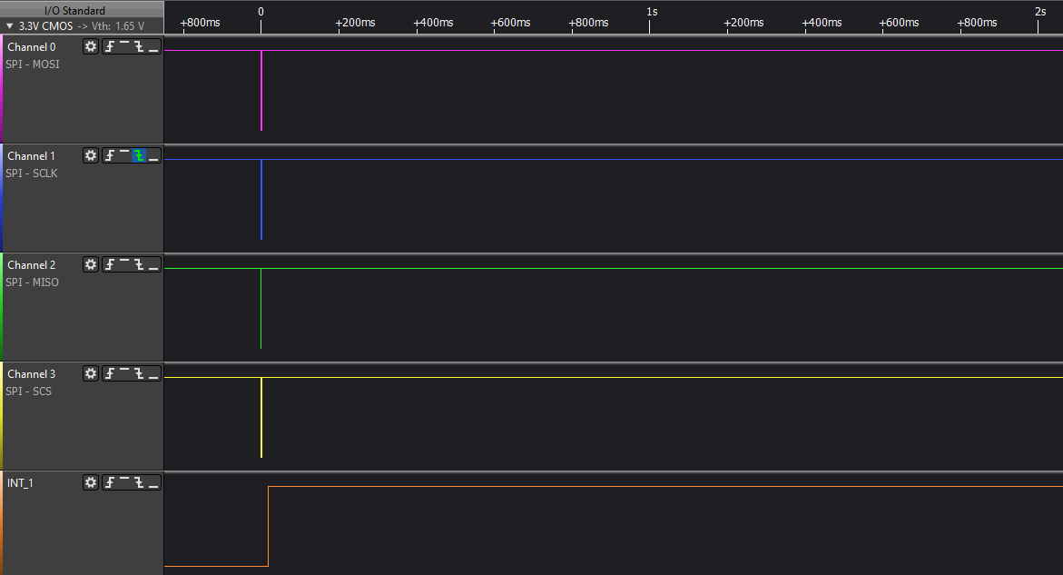
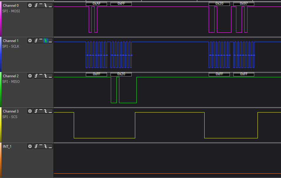
I still not getting any data in the accelerometer files. But Im pretty confident in the sam to lis3 spi comm. Heres some screen grabs of the comm. Im not familiar with accelerometers or this chip so I need to review. One thing I do notice is INT1 is staying high. I would assume this should be cleared once the sam reads the data.
Anyrate heres what I'm seeing;
Boot, post pwr reset of the 6HC and 1HCL;
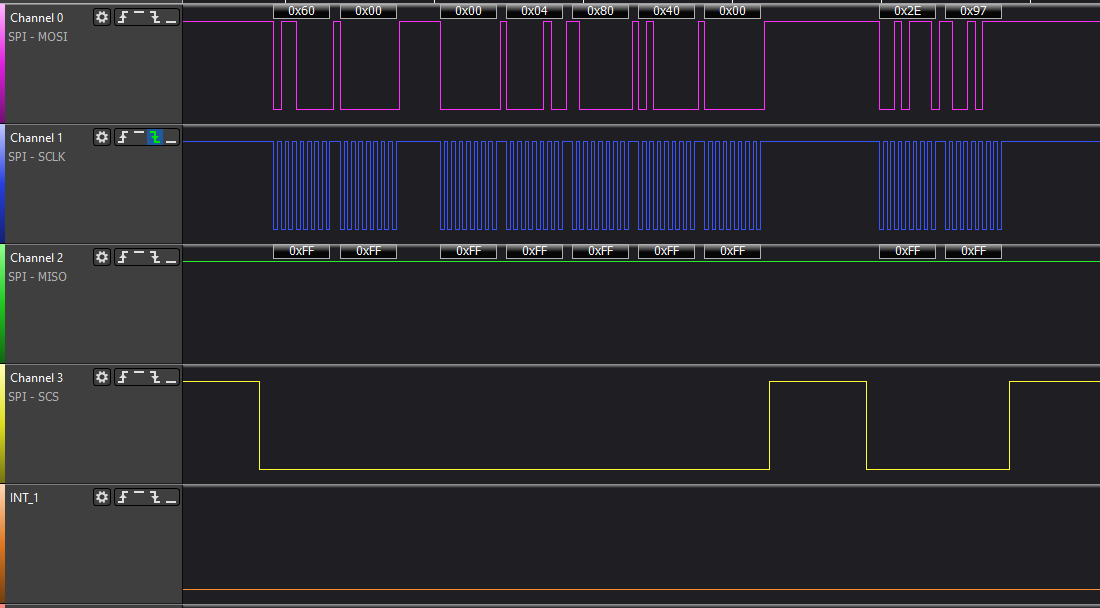
Get data
compressed
expanded
Logs
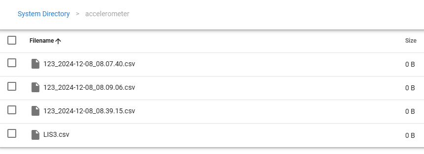
Once I do the M956 command, I am unable to repeat the command;
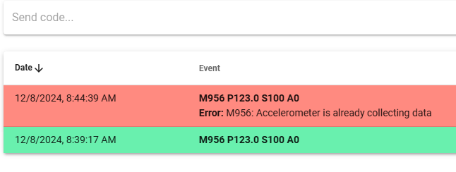
-
I got it sorted :). I was suspecting the INT pin irq was not getting called because both of my newly declared io0 and io1 pins aren't getting flagged in OM. I tried setting other gpio as inputs and the first pin I found that the OM would flag I set to the LIS3 INT1 and now everything works;
/** Doesnt work **//
//constexpr Pin Lis3dhInt1Pin = PortAPin(12);
//{ TcOutput::none,	TccOutput::tcc1_2F,	AdcInput::none,		SercomIo::none,		sercom2cPad0,		4,	nullptr 	}, // PA12

/** Works! **//
constexpr Pin Lis3dhInt1Pin = PortBPin(3);
{ TcOutput::none,	TccOutput::none,	AdcInput::adc0_15,	SercomIo::sercom5d,	SercomIo::none,		3,	nullptr		},// PB03
The proof
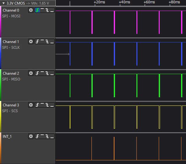

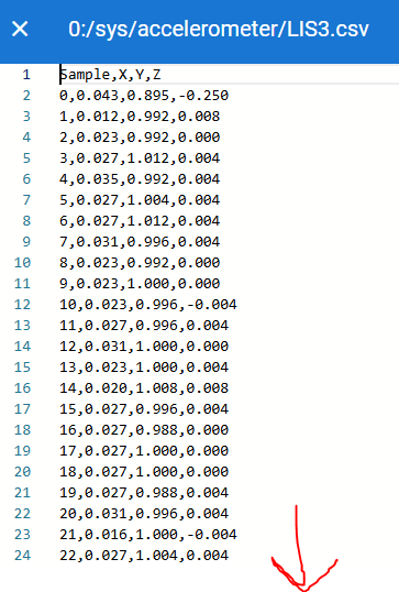
Now I just have to sort out what is going in the config.h, with none of my inputs working as I initally set. All the outputs work fine.
Any rate pleased to announce Duet3Exp SPI works
 Thanks for the help guys!
 -
 undefined wayneosdias marked this topic as a question
-
 undefined wayneosdias has marked this topic as solved
-
@wayneosdias I'm glad you u got it working.
Looking at your pin table again I see that several of the pins you remapped have the wrong Exint number. Each pin can only use a certain Exint number, which is in most cases the number of the pin within the port modulo 16. See the datasheet for details. Each pin used as an input (io_in or tacho input) needs an Exint number. Only one pin can use each Exint number. For example, PA0 PA16 and PB0 can all only use Exint 0 but it can only be assigned to one of them in the pin table, because the Exint function can only be enabled on one of them at a time.
-
@dc42 Ah ok, I thought any digital input simply had to be assigned a unique 0-15 Exint. Makes sense now. Ill review the DS and see if I can sort it out.
Thanks for the help
