Duet Safety Motor Disable
-
I'm designing a CNC-like piece of equipment. The main board is the 6HC and will have several 1HCLs.
One requirement is that during an unsafe situation determined by dedicated safety controllers, for example door open, that motors on the 1HCLs are de-energized or not able to move. This cannot rely on software or firmware. I would like to keep communication at least with the main board.
If there was a dedicated power supply input for the motors that would have solved my requirement. The safety system would just supply power when it was ok to do so.
How can I implement this with what I have?
I was thinking of supplying constant board communication power (say 12 V, 100mA through a diode) to each 1HCL. If the safety system allows movement, it will switch on a 24 V 6A power supply that is wired in series to the power on the 1HCL allowing enough current for the motors to move. The reasoning is that the constant 12V 0.1A is enough to keep canbus communication happening, but not enough current to move the motor. Does this seem like a good idea? Are there any potential issues with this?
I also read, but cannot find it anymore, on the Duet website that the canbus boards are meant to be always available (i.e. always on), but that in some cases this can be managed. Does anyone know what this means? Is there a way to reliably power down and power up 1HCLs while the main board is running?
Thanks.
-
@ChunkyPanda the version 2.0 EXP1HCL board allows the V_AUX input to act as the backup supply for most of the electronics. So you can use a contacter to remove the VIN supply when necessary for safety reasons.
Note, you should use a surge reduction thermistor in series with the VIN supply so that when you turn on the VIN supply again, the current surge is not large enough to blow the fuse.
You could cut the AC mains power to the PSU that supplies VIN instead to avoid the surge, but then you may find that the motors don't stop moving fast enough.
We still have some firmware work to do to handle loss of VIN power to the new 1HCL boards and to provide options for smooth recovery to the commanded position when VIN power is restored.
-
@dc42 Thank you for the quick response.
Oh no, I just bought 10 of the 1HCL and they are version 1.0a.
I guess I'm stuck with 1.0a for now... does it seem reasonable what I'm doing? i.e. two power supplies is parallel, 12V 0.1A with diode for constant power, and 24V 6A when motors can move?
Or is there some 1.0a board modification to get the similar V_AUX as 2.0? I'm looking at removing L3 or L4 (the inductors in series at the output of the buck) and putting 12V there, but if the above 12V 0.1A and 24V 6A works, then that is much easier.
-
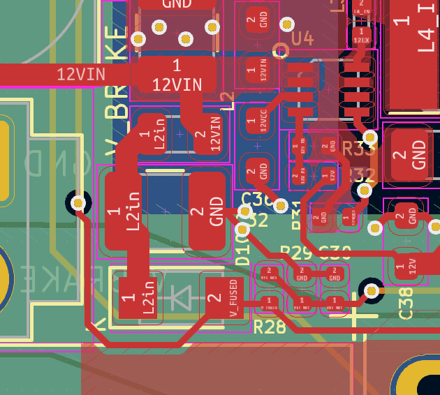
@ChunkyPanda it might be possible to modify the version 1.01a boards to provide the new functionality. If you look at the version 1.01a schematic at https://github.com/Duet3D/Duet3-Expansion-1HCL/blob/main/v1.0a/Duet3_Exp_1HCL_Schematic_v1.0a.pdf you will see a diode D10 connected between V_FUSE and C32/L2. The relevant change we made at version 2 was to add a second diode between VB_FUSED and the same C32/L2/D10 junction. This allows V_BRAKE to power the 12V regulator but not the stepper driver. The diode we use is a Schottky diode rated at 60V or greater reverse voltage and 1A or greater forward current.
-
@dc42 Thank you, that sounds great. I placed an order for a bunch of diodes and we'll see how the mod goes.
-
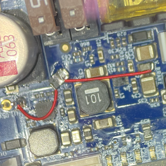
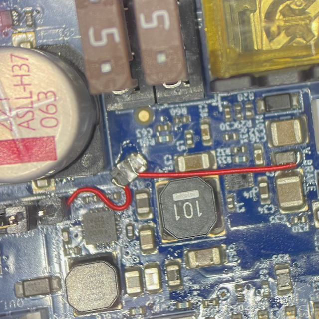
@dc42 I'm adding some photos for posterity in case this works out and someone else wants to try it.
Diode from Digi-Key... Vishay V3P6L-M3/H

The "L2in" node is only available on the top side of the PCB. I lifted the plastic bar off the "OUT_0 Select V" connector to get access to VB_FUSED and wired up the diode. Then replaced the plastic bar.

