Controlling 24V DC air solenoid with Roto Toolboard
-
Hello,
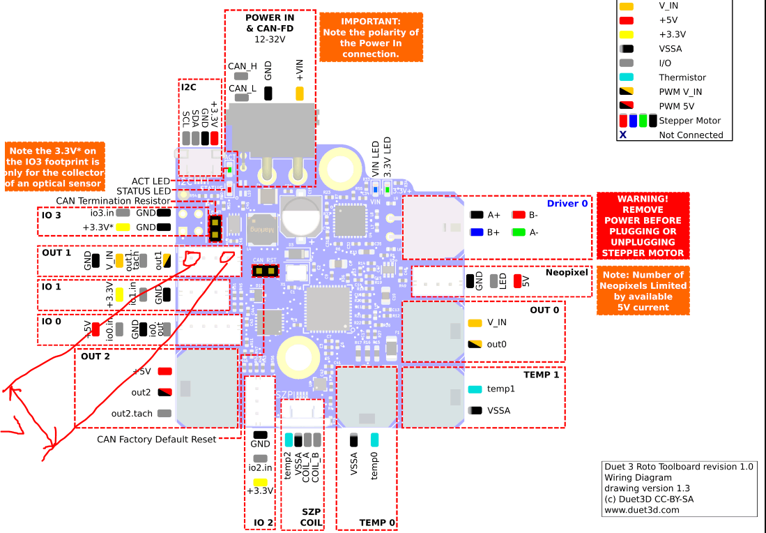
I am trying to control a 24V DC air solenoid (https://www.automationdirect.com/adc/shopping/catalog/valves/directional_control_solenoid_valves/solenoid_valves/avs-5111-24d) using the IO available on the Roto Toolboard. IO_0 is 5V only and can't use that. OUT_1 has V_IN (24V in my case) and I can use this. I see that OUT_1 is usually used for the Part Cooling Fan. I have followed this where FAN output can be repurposed as a GPIO (https://docs.duet3d.com/User_manual/Connecting_hardware/IO_GPIO)Connections as follows:
(+) of Air Solenoid --> out1 on OUT 1 in Tool RR
(-) of Air Solenoid --> GND on OUT 1 in Tool RRI have added the following line to config.g
; IO
M950 P5 C"!20.out1" Q500 ; allocate GPIO port 5 to OUT_1 on Roto-TB, 500Hz
In DWC I send the following command to activate the output
M42 P5 S1Without connecting the air solenoid and just measuring the voltage between GND and out1, I am getting only 13.95V instead of 24V.
What is the correct way to configure OUT 1 on Tool RR to be used as GP_Out?
-
@RockB the GPIO's don't regulate current so they should be outputting 24v regardless.
What are you measuring that voltage with and how are you measuring it?
Other than that your gcode looks sound -
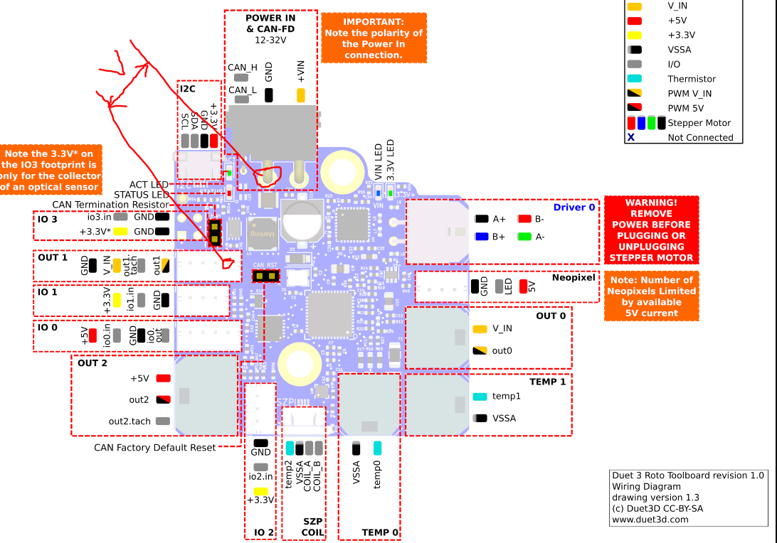
@jay_s_uk Using a multimeter with one lead on GND pin and another lead on out1 pin as shown in picture below:

-
@RockB that should just show 24v when on (unless your multimeter is struggling with the PWM signal).
You'd be better off measuring between the out1 connection on out1 and the main ground power connection on the board.
Make sure you don't short anything. -
@jay_s_uk Measuring between out1 and the main ground to the board also gives me 14V. Measuring between GND and V_IN on OUT1 gives me 24V as expected.
Since out1 is PWM at V_IN, does the Q factor in M950 affect the actual output voltage? I guess it shouldn't, but wanted to make sure.

-
@RockB said in Controlling 24V DC air solenoid with Roto Toolboard:
Since out1 is PWM at V_IN, does the Q factor in M950 affect the actual output voltage? I guess it shouldn't, but wanted to make sure
No, just the frequency that the PWM functions at. It does not reduce the voltage. If you read 14V, it's because your multimeter is smoothing out the PWM. If you set Q1 (ie 1Hz, 1 pulse per second) your multimeter might be fast enough to pick up the PWM on/off.
Ian
-
@droftarts Isn't the out1 signal the output from a mosfet switched to ground on this board? It certainly looks that way on the schematic. In which case you need to measure the voltage between out1 and V_IN not between out1 and ground. On the schematic for the roto board the pin that above is labelled as "out1" (and which is being used for the voltage measurement) is labelled as "out1_neg", which I think confirms that this PWM is switched ground.
-
@gloomyandy This makes sense given out1 is PWM switched to ground. Measuring the voltages between V_IN and out1 gives the correct voltages with M42 P5 S0 and M42 P5 S1.
I have changed my connections as follows to make it work:
(+) of Air Solenoid -->out1V_IN on OUT 1 in Tool RR
(-) of Air Solenoid -->GNDout1 on OUT 1 in Tool RR -
 undefined dc42 marked this topic as a question
-
 undefined dc42 has marked this topic as solved