stepper motor shielding with desktop sytle dc power adapters
-
Dear All,
I've been going through a lot of posts but couldn't find a clear answer, while this might be relevant to others as well.
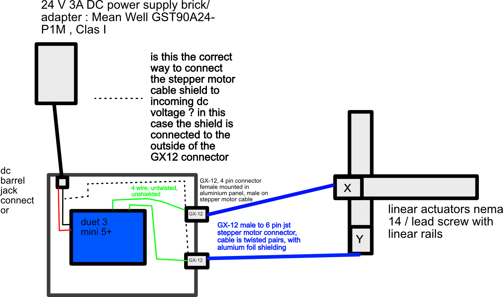
I'm designing a simple xy motion system with a duet 3 mini 5+ only two linear actuators (nema 14 running at 0.7A, leadscrew with linear rails). There is not a lot of power consumption so a 3A 24v power supply is more than enough, therefore I use these desktop power adapters (Mean Well GST90A24-P1M). The duet is housed in an anodized aluminium enclosure with only cut-outs for mounting the antenna, dc barrel adapter and female GX12 connectors. all wires inside the aluminium enclosure have ferrite chokes around them close to the board.
For the stepper motor cables, I'm using twisted pairs of cables (75cm long) with an aluminium foil shield around them and of course the black isolation. Now I think, going over all the posts about EMI / EMC, this should be sufficient, since this is only the bare minimum the duets are capable of doing, with low motor currents, twisted pair wires and ferrite chokes.
Now since the cables have shielding, I'm thinking of further improving the EMI/EMC capabilities by somehow grounding this shield, however, I'm a bit uncertain on how to do this with the power supply I've at hand. I'm not too afraid of static charges on the motor side since I'm not using any belts so I prefer to not connect the shield to the motor for aesthetic reasons
should I do it as in the following diagram? So connecting the shield to the outside of the GX-12-4pin connector, and then wiring the outside of the GX-12-4pin connector to the gnd terminal on the duet board inside the enclosure with each outside GX-12-4pin connector connected to each other?

-
@Tricep-terry yes you should ground the foil shields to the enclosure like that. Also connect the stepper motor bodies to the shield at the other end of the cables.
Duets already have EMC reduction components at the stepper motor outputs, so adding additional ferrite chokes on the outputs is probably not necessary. However it may be worth fitting a common mode choke inside the enclosure in series with the DC power input.
Exactly how you should ground the enclosure depends on the PSU but you should probably connect it to both the negative output of the PSU and to mains ground.
-
@dc42 many thanks for the response, the panels / enclosure is anodized aluminium, which is not conducting, so the gx-12 are not really in continuity with the enclosure (at least in a reliable sense), maybe if I would screw them overly tight it would. However, the enclosure is floating and no AC is coming in but only 24v DC, so grounding the whole enclosure is not necessary as far as I'm aware.
The power supply I'm using only outputs a floating DC voltage
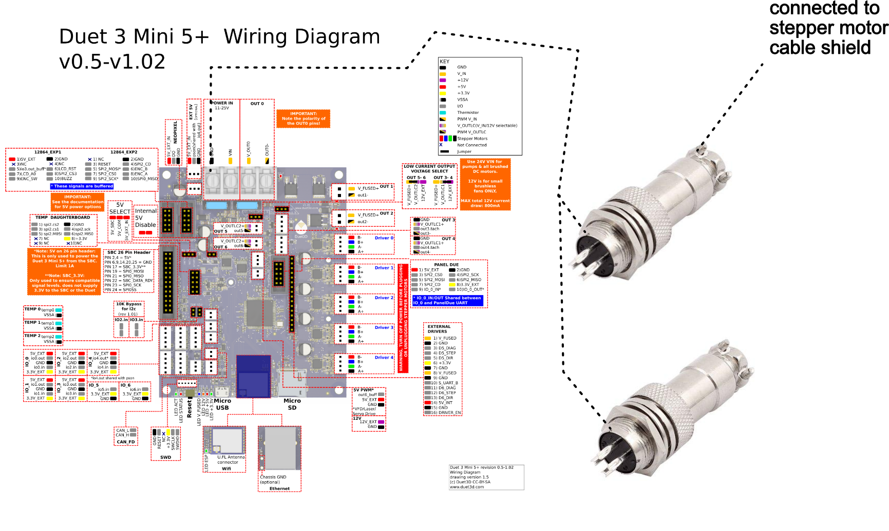
(class 1) through the barrel jack connector, therefore I'm a bit confused about your last command. Would the shield still work/be effective if it is only connected to the negative terminal of the floating 24v dc PSU as in the following image:
To me, it just looks a bit odd..
regarding connecting it to the stepper motor body, I've encountered many conflicting opinions on various build forums.. with many people saying you should only connect it to one side (controller side) so I'm still a bit in doubt about what to do with it.