Duet 3HC Expansion looses Connection
-
@Phaedrux said in Duet 3HC Expansion looses Connection:
If you leave 3hc1 disconnected are you able to get all the other boards synced with any cable combo?
Yes ,
when using a Phone cable ( 4m ) from 6XD to the rest of 3HC boards
- 6XD ---> 4m ---> 3HC2 ---> 0.5m ---> 3HC3 ---> 0.5m ---> 3HC4 ==== Sync
-
@droftarts @dc42 , I also noticed that the RJ11 Connectors (Sockets ) might be having an issue with its Pins and seem not to have a good contact with the RJ11 male connector. I know you did mention it earlier. It's hard to test but if you use several testing cables in and out of the socket you start to notice that the contact is sometimes no longer working. This might just be a side effect of me doing testing or the BOM might be revisted to have a more reliable part
-
I first deleted my post, as I did not want to offend anyone, even unwillingly, but finally I restored it: maybe it helps though.
Anyway, now it rest one more step, to put the remaining board last, and check if the first 3 (2,3,4) are ok, and the (now) forth (1) is or not syncing.
Kenable ADSL cables are simply pin to pin cables, or so it should. Only if in fact are some crossover cables they should not have worked, you need to check the colors of the wires. Still, it is not impossible to be faulty, somehow. Otherwise, for your setup, (almost) any insulated wire should work. -
@developeralgo222 ok so it does look like that 3HC needs replacing as well. please follow the same process as before with an email to warranty@duet3d.com. I suspect the 6XD may actually have been ok, but we will have to see when we get ti back for testing.
-
@T3P3Tony said in Duet 3HC Expansion looses Connection:
@developeralgo222 ok so it does look like that 3HC needs replacing as well. please follow the same process as before with an email to warranty@duet3d.com. I suspect the 6XD may actually have been ok, but we will have to see when we get ti back for testing.
The problem is that each type of cable and the Lengths i have tested somehow gives slightly different results on the Test Bench when i test individual 3HC boards with CAN Bus Terminations
6XD =====> 3HC1 or 3HC2 or 3HC3 or 3HC4 each with CAN Bus termination (Individual Tests from main board 6XD to each 3HC only)
-
Kenable ADSL 2+ Cables ( 15 meters )
3HC1 == No Sync (M122 B1 -- CAN response timeouts) , 3HC2 and 3HC4 == Sync, 3HC3 == Connects with a sync but errors (M122 B3 ) on CAN response timeouts , disconnect & reconnecting every second ) -
Straight Phone Cables ( 4 meters )
3HC1 = No Sync (M122 B1 -- CAN response timeouts) but 3HC2 , 3HC3 & 3HC4 == Sync with No Errors -
Self-Made Cat 5 or 6 with Twisted 2 pairs in use ( 5 meters )
3HC1 == No Sync at all (M122 B1 -- CAN response timeouts) but 3HC2 and 3HC4 == Sync with No Errors and 3HC3 == No Sync at all
I have decided to focus on Kenable ADSL 2+ cables because they have a bit of good insulation to avoid tagging or pulling at the RJ11 termination but Phone Cables (4m) seems to work the best ( at least i can get 3 x 3HC boards working ) .i have tested all the cables and they tested OK.
-
-
@soare0 said in Duet 3HC Expansion looses Connection:
@developeralgo222
My 2c, if allowed, as I followed the topic a little.
I only have a 6XD with 1x3HC, and they work flawlesly, and I am sure 3 of them would, if ok.
I noticed that you are not a hardware engineer, so it is understandable your... technique is not... up to standards, but yet maybe I can help.-
For such connections length, termination, shielding, twisting, is almost irrelevant, excepting the case that you would have nearby some very powerful EMI sources.
The worst thing happened was not having common ground, I smiled when noticed, bot also I saw you corrected. It is a must when you work with multiple power supply (not talking about isolation needs, when it is the case, but this is not), as we can easily have a big common mode voltage, wich may be big enough in such cases, either LF, 50Hz, or HF... xxx Hz. So, a big wire between two V- (one of each PS), is the first thing needed to be taking care of, prior to the first power up. After that, connect all the stuff exactly as you did.
Note: voltage differential may cripple some stuff on some boards, if that connexion is not in place, it is simple hazard most of the times. -
CAN is reliable enough, do not worry about it. Common mode noise/bias is another thing, and this may be troubling. But not CAN itself, as it compensates for most of this stuff, anyway.
-
I used simple telephone cable, untwisted, unshielded, and ... no problem. Even crimped myself, with a very doubtful crimping tool. Just take care to crimp hard enough... You will NOT, I repeat, you will NOT have problems with this, there is not special cable for CAN, it is a simple serial connection, with hardware/firmware specific communication protocols.
-
Just dissasemble all, and redo the test platform, as it were when working. Test each 3HC with 6XD separately, with the same cable. Then whatever one of them, changing cables. Then add the second,, with another (tested) cable, Then add the third, with the third cable. This way you will be able to separate problems.
-
If all works reliable, put the 6XD in place, and test it. Add just the first board with the first cable, and then build up until the third, retesting at each step.
Take care that you will want to repeatedly change the adresses of the boards, when testing like this, at least when testing each board, to check if each board works well on each address it would eventually be connected.
Build only step by step, even in that ... structure of yours. I very much suspect there is a problem with those metal ..... whatever, or with a cable with a loose connection. I would have the brass risers replaced by some plastic ones, even if, normally it should not matter. Mine are, I think, plated copper/brass, I need to look, maybe in some paranoia excess I changed to PE ones. Again, it should not matter, but again, maybe there is also some groove there, etc... -
Never assume it is somebody else fault (bad board, bad configuration, etc), until you can prove it. I am sorry to be blunt, but it is one of the main mistakes you did here, let name it the first. I know the drill, as I observed it SO MANY times in the past. Usually, the mechanic engineer and the electronics engineer, blame each other (most of the times the mechanics blames electronists, and most of the times they are wrong).
So the key to debug this is to check yourself at every step, do it as gradually as possible. I know this is a test engineer behaviour, wich I hardly learn from the best... -
The second mistake is that you tried to test all the system at once, without proper tools and knowledge. Now, when it works, it works, hehe, luck is luck...
-
The third mistake is to assume that you really know what you are doing. I did it many times, too. That wire, man, that wire again...!
Good luck...
Thanks for the tips but i think you are assuming a lot of things. i got a lot of help from this forum. This was my first time using Duet 3 boards on any major project and i wanted to make sure that i did it correctly so that's why i asked a lot of questions and any help. I am not new to electronics / Computer / Hardware engineering. i always welcome any suggestions or help in whatever i do, No offense.
-
-
@developeralgo222 have you tried the other plug on the 3HCs that are problematic - while one is marked in and the other out they are electrically identical

-
@T3P3Tony said in Duet 3HC Expansion looses Connection:
@developeralgo222 have you tried the other plug on the 3HCs that are problematic - while one is marked in and the other out they are electrically identical
Yes, on each 3HC board i have tested both CAN connection Sockets to confirm( both CAN_IN & CAN_OUT )
Can you confirm what Firmware binary files are required on the 6XD from Github Repo for it work properly. i know that most of this files are not used by 6XD & 3HC unless a board that requires the firmware is connected. Is there a binary file that should not be on the 6XD in this list and would cause issues ?
M20 S2 P"/firmware"
"dir": "/firmware", "first": 0, "files": [ "Duet3Firmware_EXP1HCL.bin", "Duet3Firmware_EXP1XD.bin", "Duet3Firmware_EXP3HC.bin", "Duet3Firmware_MB6HC.bin", "Duet3Firmware_MB6XD.bin", "Duet3Firmware_Mini5plus.uf2", "Duet3Firmware_TOOL1LC.bin", "Duet3_SDiap32_MB6HC.bin", "Duet3_SDiap32_MB6XD.bin", "Duet3_SDiap32_Mini5plus.bin", "DuetWiFiServer.bin", "Duet2CombinedFirmware.bin", "Duet2Firmware_SBC.bin", "Duet2_SDiap32_Maestro.bin", "Duet2_SDiap32_WiFiEth.bin", "Duet3Bootloader-SAME5x.bin", "Duet3Firmware_M23CL.bin", "Duet3Firmware_SAMMYC21.bin", "Duet3Firmware_SZP.bin", "Duet3Firmware_TOOL1RR.bin", "DuetAPI.xml", "DuetMaestroFirmware.bin", "DuetWiFiModule_32S3.bin", "PccbFirmware.bin", "Duet3_CANiap32_MB6HC.bin", "Duet3_CANiap32_MB6XD.bin", "Duet3_CANiap32_Mini5plus.bin" ], -
Ok so to focus on 3HC3.:
- Poor connections with the "Kenable ADSL 2+ Cables ( 15 meters )"
- No connection with the "Self-Made Cat 5 or 6 with Twisted 2 pairs in use ( 5 meters )"
- Good connection with the Straight Phone Cables ( 4 meters )
- Good connection with the "self-made CAT 5 & 6 Cables ( 2-pairs used) with RJ11 termination (0.5m)"?
And in all cases you have tested multiple cables of the same type with the 3HC3, with nothing else on the bus?
And those same cables work with 3HC2 and 3HC4?
-
@T3P3Tony said in Duet 3HC Expansion looses Connection:
Ok so to focus on 3HC3.:
- Poor connections with the "Kenable ADSL 2+ Cables ( 15 meters )"
- No connection with the "Self-Made Cat 5 or 6 with Twisted 2 pairs in use ( 5 meters )"
- Good connection with the Straight Phone Cables ( 4 meters )
- Good connection with the "self-made CAT 5 & 6 Cables ( 2-pairs used) with RJ11 termination (0.5m)"?
And in all cases you have tested multiple cables of the same type with the 3HC3, with nothing else on the bus?
And those same cables work with 3HC2 and 3HC4?
Yes , All cables work with 3HC2 & 3HC4. Phone cable works with 3HC2, 3HC3 & 3HC4 . All cables don't seem to work with 3HC1 at the moment. Going to try and reflash 3HC1 and test it again individually
-
@developeralgo222 yeah i am assuming for all these tests they are done individually for now.
-
@T3P3Tony said in Duet 3HC Expansion looses Connection:
@developeralgo222 yeah i am assuming for all these tests they are done individually for now.
Yes
-
@developeralgo222 Just to clarify, when you are using the boards individually are you enabling the termination resistors on the 3HC boards that is being tested?
-
@gloomyandy said in Duet 3HC Expansion looses Connection:
@developeralgo222 Just to clarify, when you are using the boards individually are you enabling the termination resistors on the 3HC boards that is being tested?
Yes , Each 3HC board is CAN Bus terminated when testing individually.
-
@T3P3Tony , @dc42 , @droftarts
Individual Bench Testing: Interesting discovery
- My first 6XD with RRF 3.5 rc3 works with 3HC1 but doesn't work with 3HC2, 3HC3, or 3HC4 but the second replacement 6XD works with 3HC2, 3HC3, or 3HC4 but not 3HC1 . How is that possible. Same cable (Phone Cable (4m) testing)
same RRF 3.5 rc3 firmware and same cable , Same bootloaders Ver 2.8 on 3HC boards. The SD Cards are a copy of each other. They have same files .
Is there anything on 6XD Version 1.01 Board that would cause this kind of issue ?
-
6XD (Initial Board) ===> 3HC1 (with CAN Bus termination ) ===> Works and Syncs without Errors
-
6XD (Initial Board) ===> 3HC2 or 3HC3 or 3HC4 (with CAN Bus termination ) ===> Does not Work and Do not Sync
-
6XD (Replacement Board) ===> 3HC1 (with CAN Bus termination ) ===> Does not Work and Do not Sync
-
6XD (Replacement Board) ===> 3HC2 or 3HC3 or 3HC4 (with CAN Bus termination ) ===> Works and Syncs without Errors
-
@developeralgo222 Thanks for doing the continued testing. I don't have an explanation for the behaviour, but it seems like there's something amiss with the initial 6XD and 3HC1. Have you already asked for a warranty replacement of 3HC1, as @T3P3Tony suggested in his earlier post here https://forum.duet3d.com/post/333134 ?
Ian
-
@droftarts said in Duet 3HC Expansion looses Connection:
@developeralgo222 Thanks for doing the continued testing. I don't have an explanation for the behaviour, but it seems like there's something amiss with the initial 6XD and 3HC1. Have you already asked for a warranty replacement of 3HC1, as @T3P3Tony suggested in his earlier post here https://forum.duet3d.com/post/333134 ?
Ian
Not yet. i was puzzled as to why 2 x 6XD boards would behave so differently while everything else is the same on the them. i also wanted to make sure that the Boards with issues , actually did not work and were defective.
Until i can have all the 4 x 3HC Expansion boards individually working with 6XD Mainboard plus having them all connected in CAN bus Net and that can be repeated with Different cables then i don't think i have any confidence at all putting them in Production on a major project.
I love the Duet Boards, Duet Open Source Project and the options offered by them but i am not gaining any confidence in the reliability of boards. I might just be unlucky and got a bad batch, what are the chances of getting 2 x 6XD boards plus 2 x 3HC might not be working correctly out of 6 boards (2 x 6XD, 4 x 3HC ) ?
MainBoard 6XD Firmware: RepRapFirmware for Duet 3 MB6XD version 3.5.0-rc.3 (2024-01-24 17:59:29) running on Duet 3 MB6XD v1.01 or later (standalone mode) 4 x 3HC Firmware and BootLoader Duet EXP3HC rev 1.02 or later firmware version 3.5.0-rc.3 (2024-01-24 17:53:31) Bootloader ID: SAME5x bootloader version 2.8 (2023-07-25) -
I don't have an explanation for the behaviour
How is that possible. Same cable (Phone Cable (4m) testing)
The CAN bus is known as robust and error-proof, even with poor cables and in harsh environments. Why on earth does this special setup want to prove us wrong? Well, let me remind you of how this all began:
Remember the famous yellow line linking V– of both PSUs together? Before being told to add that, 3 boards were supplied by one, 2 boards by the other PSU, delivering 24V each, but without any common point of reference…
Between the PSUs, the voltage levels were undefined, or, for a better understanding of what might have happened in this case, can be assumed to having been quite high.

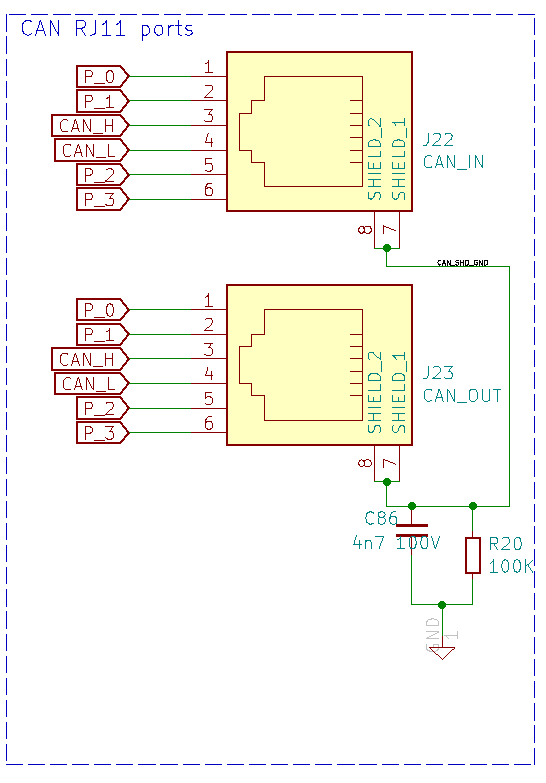
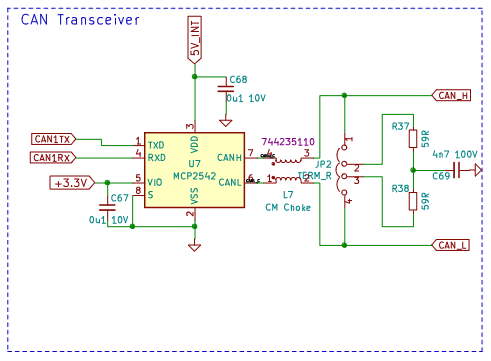
With CAN cables added, the potentials start to interact, currents flow along complex paths (see the schematics above) to establish some sort of common GND. Neither CAN ”H” nor ”L” are directly linked with V+ or V–, but: both lines go across all boards.
In other words: given the undefined potentials between two groups of boards, the voltages were negotiated via the CAN circuits - every single IC (MCP2542) or discrete component along the lines can be affected.
The ”soft” appearance of the fault(s) can be plausibly explained with a ”low current, high voltage” event, similar to what happens intentionally in EEPROMs. Else, we could observe burnt resistors or visibly damaged ICs.
Further evidence of subtle effects of the kind I described above is given by the fact that the problem spreads across at least 2 boards and depends ”somehow” on cable lengths - as if the CAN circuity has developed some kind of ”antenna sensitivity”.
@developeralgo222 said in Duet 3HC Expansion looses Connection:
I love the Duet Boards, Duet Open Source Project and the options offered by them but i am not gaining any confidence in the reliability of boards. I might just be unlucky and got a bad batch, what are the chances of getting 2 x 6XD boards plus 2 x 3HC might not be working correctly out of 6 boards (2 x 6XD, 4 x 3HC ) ?
Instead of spreading doubts about the quality of the boards or the engineering capabilities, better use Ockham's Razor: a single cause of failure is more likely to happen than multiple problems across multiple boards at once.
-
@infiniteloop said in Duet 3HC Expansion looses Connection:
I don't have an explanation for the behaviour
How is that possible. Same cable (Phone Cable (4m) testing)
The CAN bus is known as robust and error-proof, even with poor cables and in harsh environments. Why on earth does this special setup want to prove us wrong? Well, let me remind you of how this all began:
Remember the famous yellow line linking V– of both PSUs together? Before being told to add that, 3 boards were supplied by one, 2 boards by the other PSU, delivering 24V each, but without any common point of reference…
Between the PSUs, the voltage levels were undefined, or, for a better understanding of what might have happened in this case, can be assumed to having been quite high.

With CAN cables added, the potentials start to interact, currents flow along complex paths (see the schematics above) to establish some sort of common GND. Neither CAN ”H” nor ”L” are directly linked with V+ or V–, but: both lines go across all boards.
In other words: given the undefined potentials between two groups of boards, the voltages were negotiated via the CAN circuits - every single IC (MCP2542) or discrete component along the lines can be affected.
The ”soft” appearance of the fault(s) can be plausibly explained with a ”low current, high voltage” event, similar to what happens intentionally in EEPROMs. Else, we could observe burnt resistors or visibly damaged ICs.
Further evidence of subtle effects of the kind I described above is given by the fact that the problem spreads across at least 2 boards and depends ”somehow” on cable lengths - as if the CAN circuity has developed some kind of ”antenna sensitivity”.
@developeralgo222 said in Duet 3HC Expansion looses Connection:
I love the Duet Boards, Duet Open Source Project and the options offered by them but i am not gaining any confidence in the reliability of boards. I might just be unlucky and got a bad batch, what are the chances of getting 2 x 6XD boards plus 2 x 3HC might not be working correctly out of 6 boards (2 x 6XD, 4 x 3HC ) ?
I agree with you. i believe that its not the cables. And your explanation makes sense but if you have 2 PSUs that are feeding 5 boards (2 on PSU and 3 on the other ) and they are both grounded and those duet boards accept upto 24V. The initial missing connection (Jumper wire) between V- on PSU1 (24V,20A) to V- on PSU2(24V,20A) would have only affected the CAN synchronization of the Boards . Not sure why ? if they are connected independently to their respective PSU then boards would be damaged ?
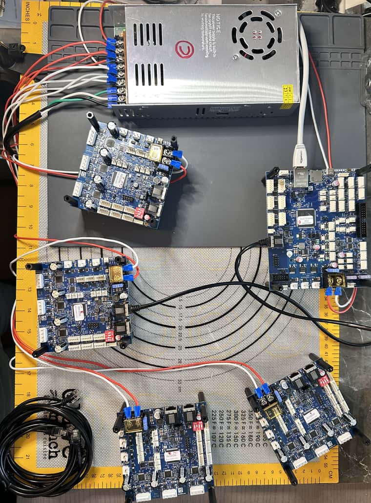
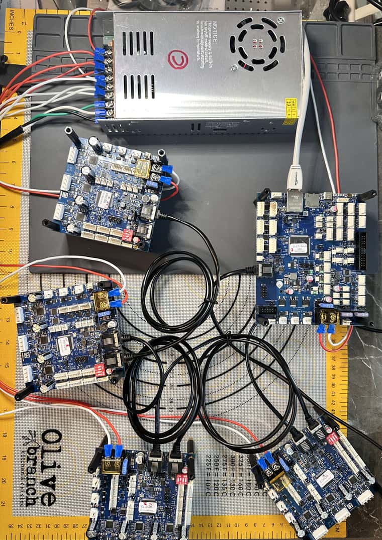
Note: The Isolated test bench has 1 PSU only, 5 Boards (6XD, 4 x 3HC) , with only VIN & GND and CAN Bus with termination connections. This is to individually test each 3HC for functionality before putting them into a CAN Bus Network.


In other words: given the undefined potentials between two groups of boards, the voltages were negotiated via the CAN circuits - every single IC (MCP2542) or discrete component along the lines can be affected.
Does that mean we have an issue with the way the CAN-FD is designed on the Duet Boards ? Does Duet boards have some protection designed in them to mitigate that issue ("undefined potential") as per your explanation above ?
-
@developeralgo222 Can you grab some photos of the can sockets?