Emergency Push Button activates on both condition
-
Greetings,
I have installed an emergency push button and connected it to io6.in of Duet 3 main board 6HC. The set-up for the button in the config.g. file is placed below.
M950 J1 C"io6.in"
M581 P1 T0 S1 R0The emergency activates in both conditions when pushed and even when the push button is reset.
How do I make the emergency activate only when it is pushed?
Is it something related to the wiring that i should check?
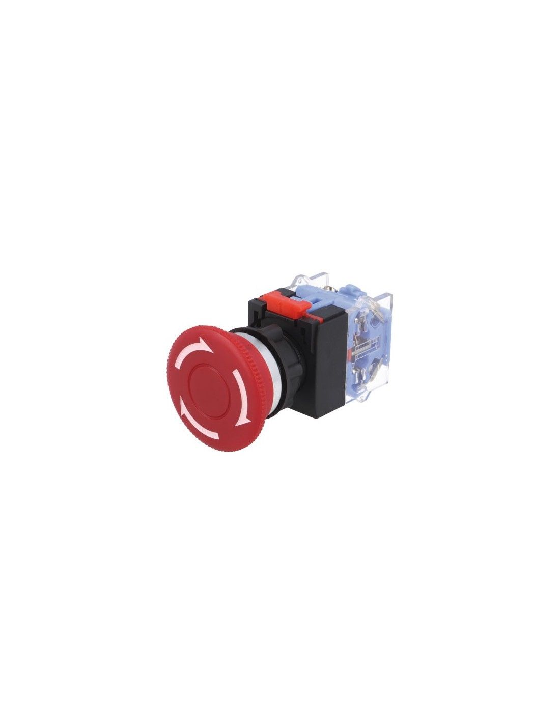
Emergency Push Button used is as shown below
Specification is LAS0-K-11TSA/RIP65 Switch emergency stop 2-position NC + NO 3A/220VAC ONPOW
 image url)
 -
The problem is inputs are not "de-bounced" which is a means for coping with the rapid opening/closing of the contacts as the switch changes state.
Consider the contact is closing - the two bits of metal come in to contact, and then they bounce apart just a tiny amount, then the contact again and maybe bounce apart again before finally coming to rest in the closed state.
This rapid change of state may be responded to by whatever the switch is connected to.
The simplest approach would be for the coders of the Duet firmware to add the bit of code needed to de-bounce an input when connected to a mechanical switch.
Until then you may have to install an external de-bounce circuit between the switch and the Duet.
Link to an article about de-bouncing a swtich
Frederick
-
@SANJR how have you wired it up? If you’ve wired it NO, could be that the floating voltage is enough to trigger between states. It may work better if you wire it NC.
Please show the wiring both ends.Also see https://docs.duet3d.com/en/User_manual/Connecting_hardware/IO_E_stop
Ian
-
@SANJR Better still, use it as it for it's intended purpose. I use the same switch but connect the 24V from the PSU to one side and the board(s) Vin to the other. Banging the switch cuts all power to the boards.
Alternatively (and arguably better still) run the mains positive to one side and then connect the PSU mains in to the other. That'll kill all power. (I can't do that on my machine because my battery UPS will cut in and supply 24V in case of mains failure).
-
@droftarts Hi
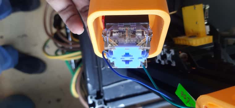
The Wiring on the emergency is coonected to the NC on the emergency pushbutton. (Image shown below) and is connected to 1o6.in and GND of the io6.in pin.
The config.g. file for the same is
M950 J1 C"io6.in"
M581 P1 T0 S1 R0
-
@SANJR As it is (I think) a simple 'connected' or 'disconnected' switch, I'd guess (like @fcwilt suggested) it is 'bouncing' when the switch is reset, at least enough to trigger again.
You can get around this by creating a trigger, using Meta Gcode, which tests the switch a second time shortly after the first press (perhaps 0.25 seconds later) to see if it is still pressed, and either continues with the emergency stop, or if it detects a false trigger, carries on. I think there's an example on the forum somewhere, but I can't find it just at the moment.
Ian
-
Create your input with something like this
Change to suit how you want trigger to workM950 J0 C"exp.e5stop" M581 T2 P0 R0 S0Create a trigger macro associated with the switch.
Note that by default if you attach your switch to trigger 0 it will do an estop.
I don't know if you can create a trigger0.g file to do the debouncing code.
Then use something like this;trigger2.g G4 P10 ; delay 10ms to debounce if sensors.gpIn[0].value = 0 echo "switch bounce detected - exit macro" M99 ; break out if sensor value is zero again (bouncing) ;we got to here so do an estop and restart M112 M999 -
I think (but my thinker may be losing it) that the T0 trigger is active during moves where the T2+ triggers are only active "between" moves.
Frederick
-
@fcwilt said in Emergency Push Button activates on both condition:
I think (but my thinker may be losing it) that the T0 trigger is active during moves where the T2+ triggers are only active "between" moves.
Frederick
You could be right. I've never tested.
I only use a trigger for a filament sensor so it's neither here nor there
If it were me I'd wire the switch to the 24v supply -
@fcwilt said in Emergency Push Button activates on both condition:
I think (but my thinker may be losing it) that the T0 trigger is active during moves where the T2+ triggers are only active "between" moves.
Frederick
Trigger 0 does an emergency stop. Trigger 1 does a pause. T2 upwards runs the associated macro. In addition R0 will allow the trigger to run at any time, R1 will only allow it to run when printing from the SD card, and R2 only when not printing.
-
@OwenD, @deckingman, @fcwilt & @droftarts Thanks
As recommended i would modify the confi.g file and create a macro file. Also shall i create a two condition the first condition when the switch triggered from S1-high to low state with T0 parameter no trigger file required.
M950 J1 C"io6.in" ; Configure pin J1 as input and assign input pin "io6.in"
M581 P1 T0 S1 R0 ; Setup Pin 1 when trigger occurs S1 from High to Low State during any time R0 for Emergemcy Push Button, no trigger.g neededAnd a second condition for the same io6.in but triggered from low to high state with T2 parameter and tigger2.g macro file
M950 J1 C"io6.in" ; Configure pin J1 as input and assign input pin "io6.in"
M581 P1 T2 S0 R0 ; Setup Pin 1 when trigger occurs S0 from Low to High State during any time R0 for Emergemcy Push Button, trigger2.g neededIn the trigger2.g macro file the meta command as suggested previously
;trigger2.g
G4 P10 ; delay 10ms to debounce
if sensors.gpIn[0].value = 0
	echo "switch bounce detected - exit macro"
	M99 ; break out if sensor value is zero again (bouncing)
;we got to here so do an estop and restart
M112
M999Is this way possible for a same pin two condition of trigger ¨S¨and different ¨T¨parameter?
-
@SANJR said in Emergency Push Button activates on both condition:
@SANJR said in Emergency Push Button activates on both condition:
................................ M950 J1 C"io6.in" ; Configure pin J1 as input and assign input pin "io6.in"
M581 P1 T0 S1 R0 ; Setup Pin 1 when trigger occurs S1 from High to Low State during any time R0 for Emergemcy Push Button, no trigger.g needed
And a second condition for the same io6.in but triggered from low to high state with T2 parameter and tigger2.g macro file
M950 J1 C"io6.in" ; Configure pin J1 as input and assign input pin "io6.in"
M581 P1 T2 S0 R0 ; Setup Pin 1 when trigger occurs S0 from Low to High State during any time R0 for Emergemcy Push Button, trigger2.g needed..................................Is this way possible for a same pin two condition of trigger ¨S¨and different ¨T¨parameter?
Yes, but you only need one M950 command.
So.....
M950 J1 C"io6.in" M581 P1 T0 S1 R0 M581 P1 T2 S0 R0 -
Thanks for the feedback