Many errors during configuration with RRF tool
-
@Phaedrux but I need already help to equilibrate the 2 z motors. How can I do?
-
Follow along with the guide here: https://docs.duet3d.com/en/User_manual/Connecting_hardware/Z_probe_auto_levelling
You need to use two separate drivers, one for each z motor. And ideally you'd have a Z probe.
-
@Phaedrux to use one of the solutions presented in the link you sent, I've to change the disposition of one of the two Z motors connected to driver outputs. Like one on Za driver and the other on E1 driver. Right?
I ask because, on my Duet 2, the Z driver has a dual socket wired in series for powering two z motors at once.
In the "Prerequisites" of the article you sent I read that: "only one of the ports can be used for independent motor leveling. Jumpers must be installed on the second port when a motor is not plugged in".
The question is: can I solve the problem using, for example, the last solution "Axis levelling using endstops", without changing the wiring of the drivers? Or am I obligated to change the wiring independently of the solution I choose to follow?
Please let me know as soon as possible. And if you need more details on my question just ask.
Many thanks.
-
@genioluiz7 said in Many errors during configuration with RRF tool:
Za driver and the other on E1 driver. Right?
Yes, that is correct.
@genioluiz7 said in Many errors during configuration with RRF tool:
Or am I obligated to change the wiring independently of the solution I choose to follow?
If you use the endstop method you still need each motor on it's own driver. A single driver can't control 2 connected motors differently.
-
@Phaedrux I followed the instructions and these are the results:
-
I can move the Z-axis (wired to the 2nd and the 4th drivers) together, and when I homed the z-axis the right and the left side stopped when they reached z and e1 endstop. So I think it is leveled. How can I check?
-
When the z-axis is homed, it's 2.5 mm under the printing surface as you can see in the pictures below. Is it a problem?
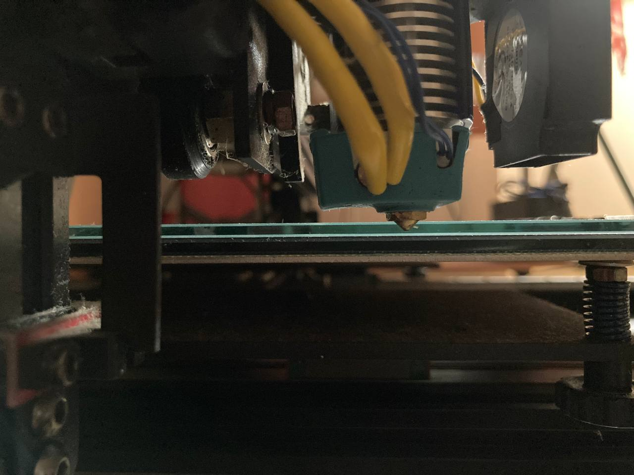
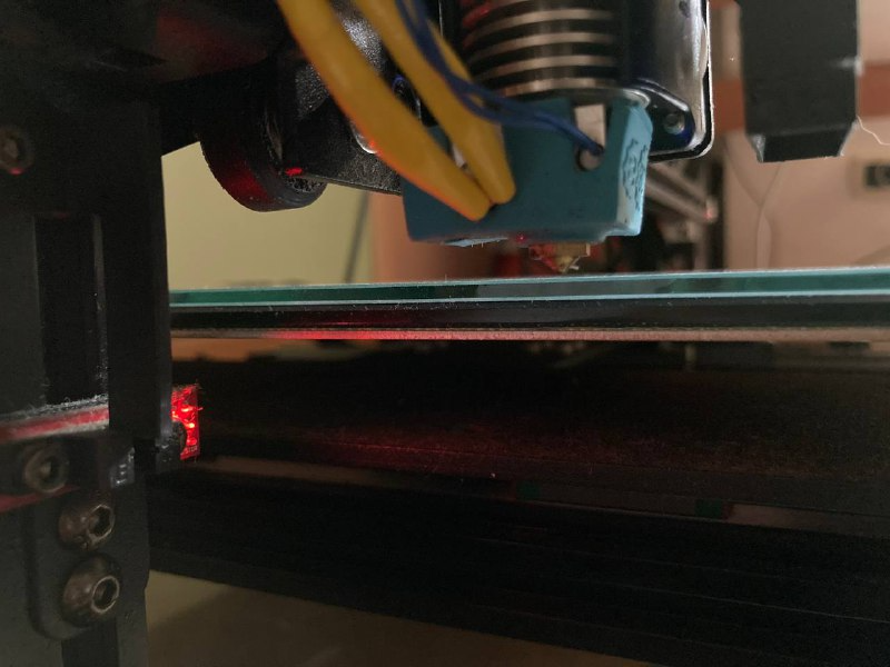
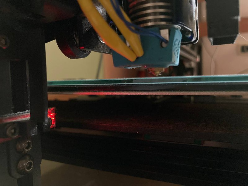
-
The homex.g and homey.g programs don't work correctly. Instead of reach each endstop, each axis moves 5 mm positively and stops, without continue to the limit. What are the problems in these .g file?
I'll repost all of them following.
; homeall.g
; called to home all axes
;
; generated by RepRapFirmware Configuration Tool v3.3.16 on Fri Aug 04 2023 19:59:42 GMT+0200 (Ora legale dell’Europa centrale)
G91 ; relative positioning
G1 H2 Z5 F6000 ; lift Z relative to current position
G1 H1 X-405 Y-405 F1800 ; move quickly to X and Y axis endstops and stop there (first pass)
G1 H2 X5 Y5 F6000 ; go back a few mm
G1 H1 X-405 Y-405 F360 ; move slowly to X and Y axis endstops once more (second pass)
G1 H1 Z-445 F360 ; move Z down stopping at the endstop
G90 ; absolute positioning
G92 Z0 ; set Z position to axis minimum (you may want to adjust this); Uncomment the following lines to lift Z after probing
;G91 ; relative positioning
;G1 Z5 F100 ; lift Z relative to current position
;G90 ; absolute positioning; homex.g
; called to home the X axis
;
; generated by RepRapFirmware Configuration Tool v3.3.16 on Fri Aug 04 2023 19:59:42 GMT+0200 (Ora legale dell’Europa centrale)
G91 ; relative positioning
G1 H2 Z5 F6000 ; lift Z relative to current position
G1 H1 X-405 F1800 ; move quickly to X axis endstop and stop there (first pass)
G1 H2 X5 F6000 ; go back a few mm
G1 H1 X-405 F360 ; move slowly to X axis endstop once more (second pass)
G1 H2 Z-5 F6000 ; lower Z again
G90 ; absolute positioning; homey.g
; called to home the Y axis
;
; generated by RepRapFirmware Configuration Tool v3.3.16 on Fri Aug 04 2023 19:59:42 GMT+0200 (Ora legale dell’Europa centrale)
G91 ; relative positioning
G1 H2 Z5 F6000 ; lift Z relative to current position
G1 H1 Y-405 F1800 ; move quickly to Y axis endstop and stop there (first pass)
G1 H2 Y5 F6000 ; go back a few mm
G1 H1 Y-405 F360 ; move slowly to Y axis endstop once more (second pass)
G1 H2 Z-5 F6000 ; lower Z again
G90 ; absolute positioning; homez.g
; called to home the Z axis
;
; generated by RepRapFirmware Configuration Tool v3.3.16 on Fri Aug 04 2023 19:59:42 GMT+0200 (Ora legale dell’Europa centrale)
G91 ; relative positioning
G1 H2 Z5 F6000 ; lift Z relative to current position
G1 H1 Z-445 F1800 ; move Z down until the endstop is triggered
G92 Z0 ; set Z position to axis minimum (you may want to adjust this); Uncomment the following lines to lift Z after probing
;G91 ; relative positioning
;G1 Z5 F100 ; lift Z relative to current position
;G90 ; absolute positioning -
-
@genioluiz7 For X and Y, test the endstops are working correctly, and adjust the config.g code as needed. See https://docs.duet3d.com/en/How_to_guides/Commissioning#h-8-check-endstops
For Z, as you are using endstops at the minimum end of travel and not a Z , either physically move the endstops up, which would be a good idea to stop the nozzle hitting the bed, or adjust the bed down.
Ian
-
@droftarts How much do I move the endstop up? Just on the same level of the surface or a little bit upper or lower?
-
Well you want it to stop before the nozzle hits the bed. You want Z0 to be when the nozzle is touching the bed. If you have a gap, you can edit the homez.g or homeall.g to mark the Z axis at a position that takes that gap into account. So if it stops when it's 1mm above the bed surface, you can add G92 Z1 to just after your z homing move to tell the firmware that the nozzle is 1mm above the bed.
-
@genioluiz7 the endstop can’t be physically above the bed surface, or it will stop the nozzle reaching bed surface. Can your bed be adjusted? If so, I’d move the endstops to a point where the bed is halfway on its adjustment. You also need to get the endstops level, so the gantry is level, then level the bed to the nozzle.
Realistically, this isn’t a good way of homing Z; there’s too many things that could go wrong and cause a nozzle crash.. A Z probe would be a much better idea. Or set the endstops at the maximum end of the Z axis, home to there, and adjust M208 for the maximum travel. This also means recovery after a power failure mid print is easier, as you can home Z without hitting the print.
Ian
-
@droftarts Ok many thanks for your help. Now I've tried to launch a Chiron level test. Seem that the plate dimension or position is not understand from the start of the process. See the following picture maybe is better to show you the problem.
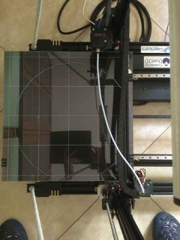
-
When you move the nozzle to the 0,0 XY position where does the nozzle actually end up on the bed? You likely need to adjust your M208 values such that the 0,0 point is on the front left corner of the printable area. If the endstops move the nozzle off the printable area of the bed, you can use a negative value for the M208 minima. (assuming the XY endstops are on the low end)
-
@Phaedrux many thanks for your help. I solved almost every issue. One of the remaining is the following.
When the right z motor get the position between 3.50 mm and 6 mm seems like is loosing power, and next the axis rotate backwards, while the left z motor remain stopped.
What do you think, is the problem hardware or software?- First position
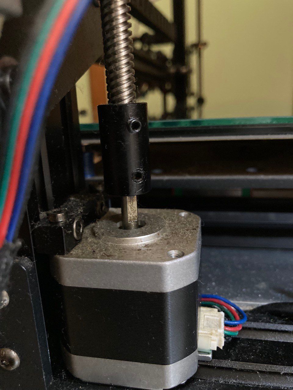
- second position
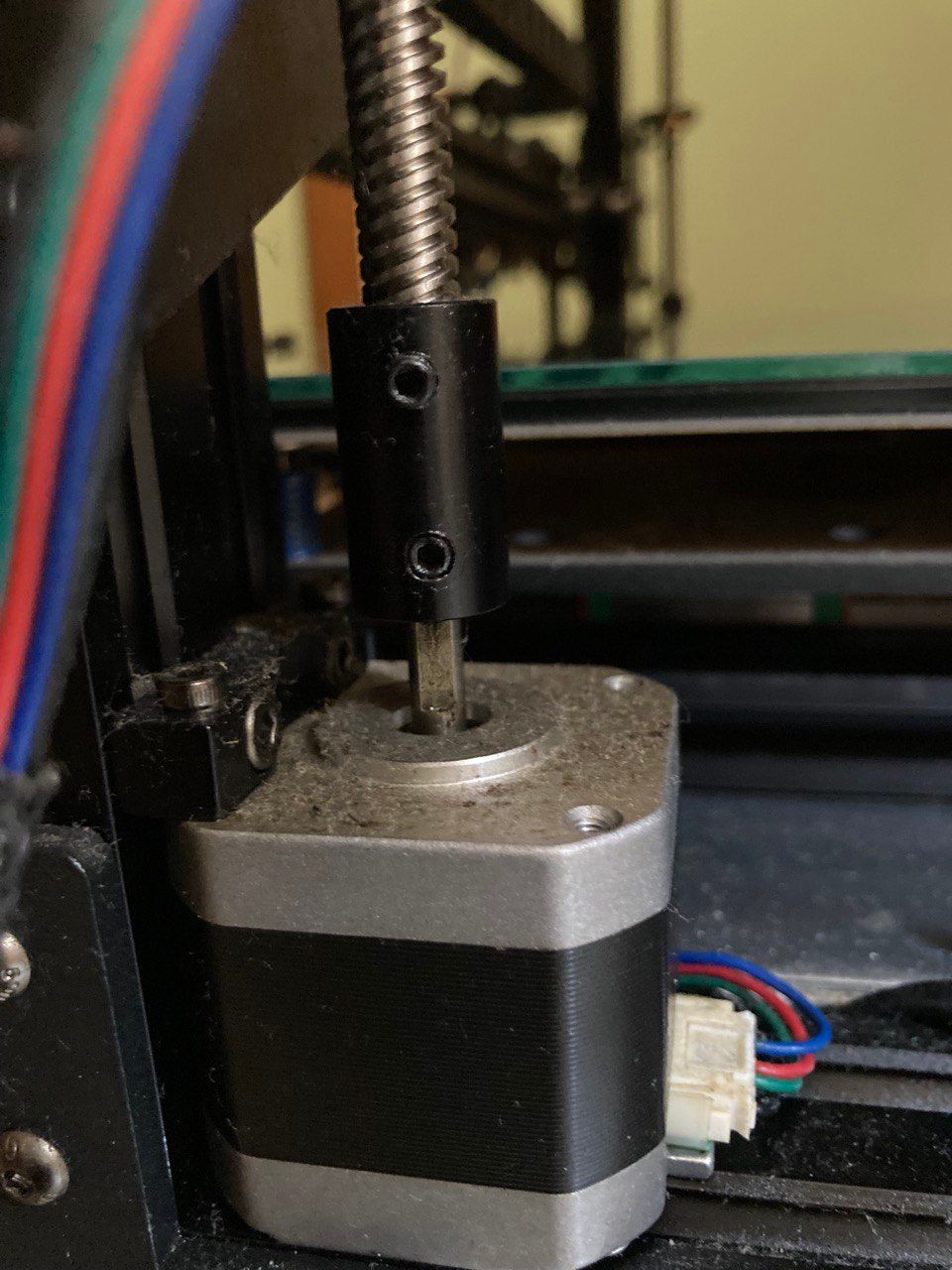
- problem
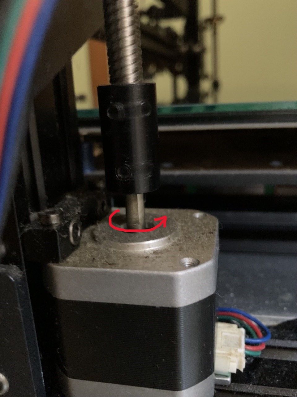
- First position
-
@genioluiz7 said in Many errors during configuration with RRF tool:
z motor
Remind me how you have your z motors connected to the duet and how they are configured in config.g.
It may be that your motor current is set too low. Do you know the rated max current for those motors?
-
@Phaedrux said in Many errors during configuration with RRF tool:
Remind me how you have your z motors connected to the duet and how they are configured in config.g.
The right z motor is connected to Driver 2/ZA with the jumpers
The left to Driver 4/E1 motor.I post all the config.g but I think that what you ask for is only this one:
"M906 X800 Y800 Z800 E800 ; set motor currents (mA)
M84 S0 ; Disable motor idle current reduction"; Configuration file for Duet WiFi (firmware version 3.3)
; executed by the firmware on start-up
;
; generated by RepRapFirmware Configuration Tool v3.3.16 on Fri Aug 04 2023 19:59:42 GMT+0200 (Ora legale dell’Europa centrale); General preferences
M575 P1 S1 B57600 ; enable support for PanelDue
G90 ; send absolute coordinates...
M83 ; ...but relative extruder moves
M550 P"Chiron" ; set printer name; Network
M552 S1 ; enable network
M586 P0 S1 ; enable HTTP
M586 P1 S0 ; disable FTP
M586 P2 S0 ; disable Telnet; Drives
M569 P0 S0 ; physical drive 0 goes backwards
M569 P1 S0 ; physical drive 1 goes backwards
M569 P2 S0 ; physical drive 2 goes backwards
M569 P3 S1 ; physical drive 3 goes forwards
M569 P4 S0 ; physical drive 4 goes backwards
M584 X0 Y1 Z2:4 E3 ; set drive mapping
M350 X16 Y16 Z16 E16 I1 ; configure microstepping with interpolation
M92 X80.00 Y100.00 Z400.00 E420.00 ; set steps per mm
M566 X900.00 Y900.00 Z60.00 E120.00 ; set maximum instantaneous speed changes (mm/min)
M203 X6000.00 Y6000.00 Z180.00 E1200.00 ; set maximum speeds (mm/min)
M201 X500.00 Y500.00 Z20.00 E250.00 ; set accelerations (mm/s^2)
M906 X800 Y800 Z800 E800 ; set motor currents (mA)
M84 S0 ; Disable motor idle current reduction; Axis Limits
M208 X-15 Y-15 Z0 S1 ; set axis minima
M208 X400 Y400 Z440 S0 ; set axis maxima; Endstops
M574 X1 S1 P"!xstop" ; configure switch-type (e.g. microswitch) endstop for low end on X via pin xstop
M574 Y1 S1 P"!ystop" ; configure switch-type (e.g. microswitch) endstop for low end on Y via pin ystop
M574 Z1 S1 P"zstop+e1stop" ; configure active-high endstop for low end on Z via pin zstop and e1stop; Z-Probe
M558 P0 H5 F120 T6000 ; disable Z probe but set dive height, probe speed and travel speed
M557 X15:385 Y15:385 S20 ; define mesh grid; Heaters
M308 S0 P"bedtemp" Y"thermistor" T100000 B4138 ; configure sensor 0 as thermistor on pin bedtemp
M950 H0 C"bedheat" T0 ; create bed heater output on bedheat and map it to sensor 0
M307 H0 B0 S1.00 ; disable bang-bang mode for the bed heater and set PWM limit
M140 H0 ; map heated bed to heater 0
M143 H0 S120 ; set temperature limit for heater 0 to 120C
M308 S1 P"e0temp" Y"thermistor" T100000 B4138 ; configure sensor 1 as thermistor on pin e0temp
M950 H1 C"e0heat" T1 ; create nozzle heater output on e0heat and map it to sensor 1
M307 H1 B0 S1.00 ; disable bang-bang mode for heater and set PWM limit
M143 H1 S285 ; set temperature limit for heater 1 to 285C; Fans
M950 F0 C"fan0" Q500 ; create fan 0 on pin fan0 and set its frequency
M106 P0 S0 H-1 ; set fan 0 value. Thermostatic control is turned off
M950 F1 C"fan1" Q500 ; create fan 1 on pin fan1 and set its frequency
M106 P1 S1 H1 T45 ; set fan 1 value. Thermostatic control is turned on; Tools
M563 P0 D0 H1 F0 ; define tool 0
G10 P0 X0 Y0 Z0 ; set tool 0 axis offsets
G10 P0 R0 S0 ; set initial tool 0 active and standby temperatures to 0C; Custom settings are not defined
; Miscellaneous
M501 ; load saved parameters from non-volatile memory
M911 S10 R11 P"M913 X0 Y0 G91 M83 G1 Z3 E-5 F1000" ; set voltage thresholds and actions to run on power loss -
@genioluiz7
Maybe E800 is the current for Driver 3/EO motor (the extruder)
and we need to add
the current for Driver 4/E1M906 X800 Y800 Z800 E800; set motor currents (mA)
-
@genioluiz7 said in Many errors during configuration with RRF tool:
M906 X800 Y800 Z800 E800; set motor currents (mA)
No that's correct for setting motor current. It's per axis, not motor.
Are both Z motors identical?
Do you know the rated max current for the motors?
Do they have a model number?In the config that Herve shared above, he is using M906 Z1000 instead of 800, perhaps your current is set a bit low.
Are your lead screws lubricated?
-
M906 X800 Y800 Z1000 E800 I50 ; set motor currents (mA) and motor idle factor in per cent
-
Are both Z motors identical?
Yes, they are. I measured them, both are 4x4x4 cm -
Do you know the rated max current for the motors?
Unfortunately not. How can I reach that information? -
Do they have a model number?
Not, I tried to find that number also on the x, y and E motor because seems that they are the same but nothing. The only thing that I noted is on the E motor, what you se in the following picture. Maybe it can help.
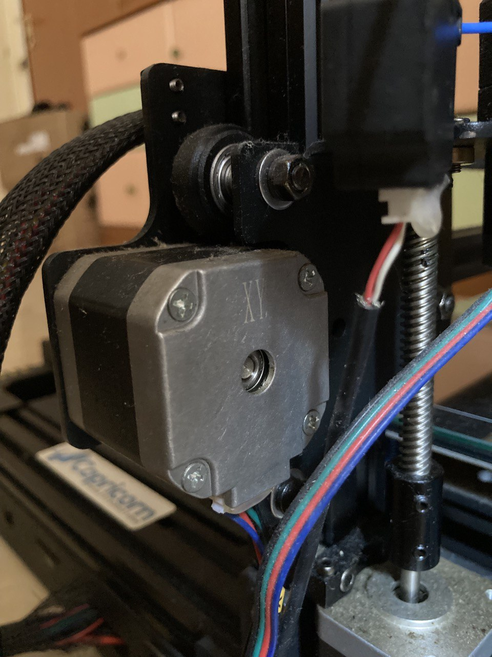
I'm refearing to that XY on the bottom of the motor. -
Are your lead screws lubricated?
Yes -
In the config that Herve shared above, he is using M906 Z1000 instead of 800, perhaps your current is set a bit low.
Maybe you're right. This is the Herve M906
M906 X800 Y800 Z1000 E800 I50 ; set motor currents (mA) and motor idle factor in per centInstead in my M906
M906 X800 Y800 Z800 E800 ; set motor currents (mA)Do I need the Idle factor?
I'll post also the old config file of Duet. This is the one before I updated the firmaware.
About this config:
- It was set by the previus owner of the chiron
- I don't know if it is correct
- the firmware version is 1.21
; Configuration file for Duet WiFi (firmware version 1.21)
; executed by the firmware on start-up
;
; generated by RepRapFirmware Configuration Tool on Wed Nov 07 2018 17:54:35 GMT+0100 (centraleuropeisk normaltid); General preferences
G21
G90 ; Send absolute coordinates...
M83 ; ...but relative extruder moves; Network
M550 PChiron ; Set machine name
M552 S1 ; Enable network
M586 P0 S1 ; Enable HTTP
M586 P1 S0 ; Disable FTP
M586 P2 S0 ; Disable Telnet; Drives
M569 P0 S0 ; Drive 0 X goes backwards
M569 P1 S0 ; Drive 1 Y goes forwards
M569 P2 S0 ; 1st-zmotor (original Z) goes forwards
M569 P3 S0 ; 2nd-zmotor - Normally used as Extruder 1
M569 P4 S1 ; Extruder 0 goes forwards;Remapping drivers for axis Z 2-3 drivers
M584 X0 Y1 Z2:3 U3 E4 P3 ; Driver 0 For X, 1 for Y, Z=2:3 U=4, Extruder 4 P3 not show U axis in GUI; Movement setting
M92 X80 Y100 Z400 U400 E415.00 ; Step/mm X Y Z U E
M350 X16 Y16 I1 ; Configure microstepping with interpolation 256
M350 Z16 I1 ; Configure microstepping with interpolation 256
M350 E16 ; Configure microstepping without interpolation
M566 X700 Y700 Z300.00 U300.00 E1000.00 ; Set maximum instantaneous speed changes (mm/min) (Jerk)
M203 X12000 Y12000 Z300.00 U300.00 E12000 ; Set maximum speeds (mm/min) UU
M201 X1500 Y1500 Z50.00 U50.00 E5000.00 ; Set accelerations (mm/s^2)
M906 X1000.00 Y1000.00 Z1000.00 U1000.00 E900.00 I30 ; Set motor currents (mA) and motor idle factor in per cent
M84 S30 ; Set idle timeout; Axis Limits
M208 X-12 Y-11 Z0 U0 S1 ; Set axis minima
M208 X426 Y410 Z450 U450 S0 ; Set axis maxima; Endstop
M574 X1 Y1 S0 ; Set Endstop and S signal
M574 Z1 U1 S1 ; Set Endstop and S signal; Heaters
M307 H2 A319.7 C159.5 D5.1 V24.3 ; Set Pid parameters for hot end H2
M307 H0 A90.0 C700.0 D10.0 V0.0 B0 ; Set Pid parameters for Bed H0
M305 P0 T100000 B4138 C0 R4700 ; Set thermistor + ADC parameters for heater 0 Bed
M143 H0 S120 ; Set temperature limit for heater 0 to 120C
M305 P2 T100000 B4725 C0.0000000706 R4725 ;T100000 B4138 C0 R47OO
M143 H2 S285 ; Set temperature limit for heater 1 to 285C; Fans
M106 P0 S0
M106 P1 S255 T45 H2; Tools
M563 P0 D0 H2 ; Define tool 0
G10 P0 X0 Y0 Z0 ; Set tool 0 axis offsets
G10 P0 R0 S0 ; Set initial tool 0 active and standby temperatures to 0C; Set differential temperature MCU - AMBIENT
M912 P0 S1; Automatic power saving
M911 S10 R11 P"M913 X0 Y0 G91 M83 G1 Z3 E-5 F1000" ; Set voltage thresholds and actions to run on power loss; Custom settings are not configured
T0
Many thank for your precious help.
-
-
@genioluiz7 said in Many errors during configuration with RRF tool:
M906 X1000.00 Y1000.00 Z1000.00 U1000.00 E900.00 I30 ; Set motor currents (mA) and motor idle factor in per cent
They were using higher motor currents, so it would be worth trying the higher values.
-
@Phaedrux
Do I need to insert the idle factor? -
@genioluiz7 said in Many errors during configuration with RRF tool:
Do I need to insert the idle factor?
If you want to reduce the motor current when idle, yes.