Issue flashing firmware/connecting with ICE, Toolboard 1LC
-
@rl_at_berk said in Issue flashing firmware/connecting with ICE, Toolboard 1LC:
I am ignoring the reset pin (leaving unconnected).
The ICE need the Reset pin connected in order to flash the firmware.
-
@dc42 Connecting the reset pin didn't do anything. Some more details:
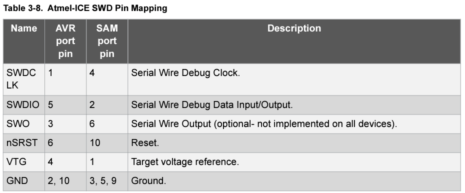
The Ice pinout I am using is the following:

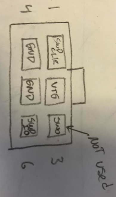
This goes to a 6-pin connector, which I am connecting to the 5pin SWD pads on the toolboard (toolboard v1.3), which has the following pin configuration (pin 1 is SWDCLK, Pin 2 is target voltage):

The reset pin on the toolboard does not have a place on the cable that came with the ICE according to this, so I manually connected it to the Reset pin on the ICE. This did nothing.In the device programmer (microchip studio), I have the following config: Atmel-ICE, ATSAMC21G18A, SWD. This still reads the Target voltage correctly but errors with No Device Detected, Error 4109.
-
@rl_at_berk the cable with the 6 pin connector is probably intended for programming AVR devices using the AVR connector on the ICE.
-
@dc42 I was finally able to flash firmware to the toolboard over SWD, but now I am unable to connect to the toolboard via CAN. This could probably be a different question but I am posting here, let me know if I should make a separate thread.
I reflashed the bootloader: not the most recent, as the toolboard rejected every 2.X version (status light flashed twice and turned off) I had to go with 1.3. Once I had that, I flashed both the firmware_TOOL1LC and TOOL1LC-Debug. These are from a RRF2 build, I cannot use RRF3 because of an existing project I am working with. Both flashed, but I could not do anything with CAN once I flashed. The debug version caused the status light to flash rapidly, and I could not connect via CAN. The regular firmware caused the status light to turn off and not turn back on. In both firmware's, the factory reset (hold both buttons while turning on) did nothing. CAN address is 121.
I am using a Mainboard 6HC v1.02. I verified that both terminating resistors are in the CAN circuit, and I hooked up the mainboard CAN to an oscilloscope and saw CAN messages being sent, as expected. But, I am unable to communicate with the toolboard.
Thoughts? Thanks.
-
@rl_at_berk said in Issue flashing firmware/connecting with ICE, Toolboard 1LC:
I reflashed the bootloader: not the most recent, as the toolboard rejected every 2.X version (status light flashed twice and turned off)
In what way did it reject the 2.X versions? Do you mean that Atmel ICE reported failure? Older bootloaders do not support the version 1.3 tool board.
There is a specific sequence needed to re-flash the bootloader:
- Disconnect the board from the CAN bus (so that it cannot load firmware, which would reinstate the bootloader protection)
- Run Erase All in Atmel Studio. This erases the main firmware but not the bootloader.
- In the Fuses section set the bootloader protection amount to zero
It should then be possible to flash and verify the bootloader, or to flash the Debug build of the tool board firmware.
@rl_at_berk said in Issue flashing firmware/connecting with ICE, Toolboard 1LC:
These are from a RRF2 build
We didn't support CAN officially in any RRF 2.x release. You will need to upgrade to RRF 3.x in order to use a CAN-connected tool board.
-
@dc42 I wrote Bootloader 2.3 to the toolboard and had it verify (I think the problem I had before was I forgot to write the fuses to the board). I put a RRF3 build of the code, with build configurations all matching SAMC21 or TOOL1LC. (CANlib - SAMC21RTOS, CoreN2G - SAMC21-CAN, Duet3Expansion - TOOL1LC, FreeRTOS - SAMC21, RRFLibraries - SAMC21) I put the bin file onto the mainboard in the /firmware folder. When I flash the bootloader onto the toolboard over SWD following the steps you gave above (no connection to mainboard at this point), microchip studio verifies everything is OK. The status light on the toolboard then flashes twice, indicating invalid firmware. a second later it flashed four times, indicating the board attempted to reach out to the mainboard and failed.
Next, I powered off the board, plugged in the CAN to the mainboard, and powered on both boards. The toolboard waits for a second and then pulls the firmware from the mainboard, and the status and act lights clearly indicate that the firmware is being written. Then, the status lights blinks repeatedly and fast, indicating no CAN connection. I cycled power and still no CAN connection. This does not make sense to me, as the toolboard flashed its own firmware over CAN, did it not?
thanks for your help
-
@rl_at_berk which main board and tool board firmware versions are you using?
-
@dc42 Duet3 Mainboard 6HC v1.02 with firmware 3.4.5 (date 2023-06-06)
Toolboard v1.03 with firmware 3.4.4 -
@rl_at_berk those are compatible firmware versions so that does indeed seem odd. As the bootloader is able to load firmware from the 6HC, CAN communication must be working. So unless one of the firmware binaries is corrupted in some way (in which case we would expect the LED to flash a CRC error code), they should work together.
Does the tool board factory reset procedure result in it loading firmware over CAN again?
-
@dc42 Found the solution, I didn't realize this earlier but the Toolboard firmware I was using had actually been modified by a coworker. We bought a new toolboard and tried to connect CAN (thinking maybe an IC had been fried) and it worked, so we copied that firmware onto the toolboard I had been using and sure enough, works fine. So it was a software issue. Thanks for your help!
-
 undefined dc42 marked this topic as a question
-
 undefined dc42 has marked this topic as solved