Wiring Help Request: Wanhao i3 Plus (16-Pin IDC)
-
Hello, I'm stuck on a particular challenge to do with the Electronics.
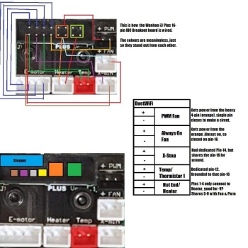
Wanhao i3 Duplicator Plus, DuetWiFi Upgrade.The Wanhao's Stepper Motor, Heater, Thermistor, X-Stop, and 2 fans, are connected to the body via a 16-pin IDC connector.
Originally, this cable connects directly to the Stock controller board.I am trying to figure out which of the 16 IDC wires should go where, on the DuetWifi board.
The Stepper motor was easy to figure out, since they are just pin to pin. (9, 11, 13, and 15).
However, as i stare at the diagram I made, I am unsure exactly where to connect the other peripherals, since some pins are shared.
This means that for these connections, polarity 'does' matter.I feel like this is an easy task for someone who's mind is 'wired' this way, so thought I'd ask here if someone can join the dots for me, in the bottom of this diagram.
Thanks

-
-
Here's a video To explain a little better.
(I had originally sent to a friend, hence the wording) -
Here's a photo of the inside, showing the original board and connector… and my IDC cable that'll be used instead.
The white connector is the Extruder stepper motor.
Easy enough to figure out as the wires are independent... or patched... parallel.. -
What I can see from the diagram is:
1. The hot end fan, print cooling fan and the heater share a common +ve connection. That's the 4 pins with the orange square around it in your diagram, This is no problem, assuming that you are not trying to run them from different voltages. You can connect those 4 wires to the VIN side of the E0 terminal block. Caution! On most Duet PCB revisions, the E0- and VIN labels on those pins are the wrong way round. The VIN side of the 2-pin terminal block is nearest the edge of the board that has the USB connector and SD card. Then you can wire the heater- connection to the other pin of the E0 terminal block, and the print cooling fan negative terminal (which you marked with a yellow line) to the Fan- pin on the FAN0 connector.
2. The hot end fan negative terminal, thermistor ground wire and endstop switch ground wire share a common pin (bottom left pin in your diagram). This is poor design, because it will affect the accuracy of the temperature reading at higher temperatures, and if the wire breaks then it will feed 12V or 24v via the fan into the thermistor input and the endstop input. So my recommendation is that you replace this by 3 separate wires (then you would also be able to control the hot end cooling fan thermostatically). But if you want to try a common ground, you can connect it to the ground pin of the X endstop connector. Then the other X endstop connector wire goes to the STP pin on the same connector, and the thermistor wire goes to the E0 R(th) pin of the thermistor connector.
HTH David


