6XD - AC Servo drive (single-ended and differential signal)
-
@dc42 Hello,
I can reach 3000RPM in 700mm movement (it can go even more in tunning SW, but I will stay at 3k Max) = 50RPS = 14 BallScrew Rotations in 700mm = 700mm/0.28s
One Ballscrew rotation is 50mm:
For precision 0.01mm (Servo "gear" 5000 / 50mm = 100steps/mm):
700mm in 0.28s = 14 BallScrew rotations x (Servo "gear" 5000 steps for one Ballscrew rotation) = 70000 steps in 0.28s or 250000 steps/sFor precision 0.02mm (Servo "gear" 2500 / 50mm = 50steps/mm):
700mm in 0.28s = 14 BallScrew rotations x (Servo "gear" 2500 steps for one Ballscrew rotation) = 35000 steps in 0.28s or 125000 steps/sMaybe I did something wrong here, but that is a lot of steps!


Br,
-
@Zdenko so you are looking to achieve 250k steps/second. The standard 6XD timing parameters won't provide more than about 180k steps/sec. So you will need to use shorter timing parameters. Try using T1.3:1.3:1:1.3 in the M569 commands for all six drivers, including any that you are not using. Also add the 1K pullup resistors between each STEP or DIR output of the Duet and +5V.
-
@dc42 Hello,
Thank you for your support,
I have done all the steps according to your input, even 1k PullUp to +5V on STEP outputs for X and Y.
Now I even managed to hit over 3100RPM with 0.01mm precision.
https://www.youtube.com/watch?v=XpU1aV3POuQ&ab_channel=ZdenkoStanec
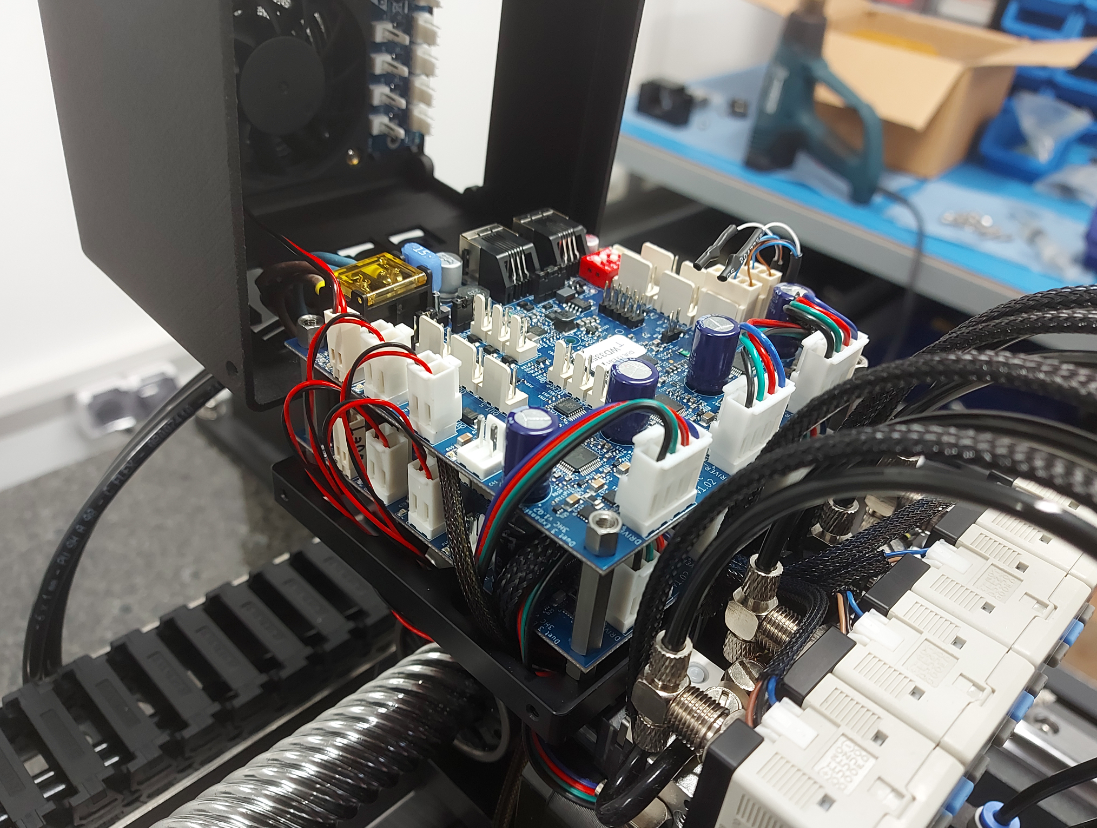
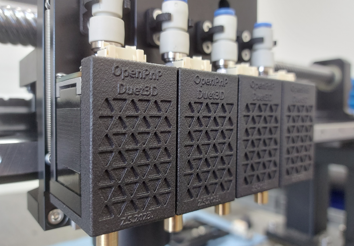
Some pictures if someone is interested in how the Head looks inside.
P.S. I removed the M4 metal stand off-s as this can result in a short circuit of motor phases.


Some details
 :
:
Thank you,
-
@Zdenko I'm glad you got it working. I suggest you check that you don't get a 0.02mm position shift every other time you change direction. If you do then you probably need 1K pullup resistors on the X and Y DIR lines too.
So it's a pick and place machine?
-
@dc42 Hi,
I will just put 1k on DIR pins also, to be on a safe note.

Yes, this is my second revision of the Pick and Place machine, I am currently working on a conveyor system for it and later I need to implement feeders.
-
@dc42 Hi,
After further testing, it seems that I am actually getting position shifts, it is quite random, sometimes only in X and sometimes only in Y, and sometimes X and Y. Shift warry from 0.02mm to almost 0.2mm on long-distance moves.
Wires from 6XD to Servo drivers are around 30cm, and both X and Y have pull-up resistors on STEP and DIR.
For a test, I changed T1.3:1.3:1:1.3 to T1.4:1.4:1:1.4 and T1.5:1.5:1:1.5, it works good but I need to reduce the overall acceleration speed, it seems I will need to change overall precision to 0.02mm in the end If I want to move that fast and in a repeatable way.

Thank you,
-
@Zdenko try leaving rhe first two T values at 1.3 and increasing the last two back to 2.7.
If that doesn't work, try T1.0:1.6 :2.7:2.7.
-
@dc42 Hi,
T1.3:1.3 :2.7:2.7 is not working, the same random shifts unfortunately.
T1.0:1.6 :2.7:2.7 works much better, I am getting on Long-distance move around 0.01mm shift on X-Axis in negative (so it is losing steps), so in 10 Long-distance moves I lose around 0.1mm in X axis.
Long-distance movement is machine Max Diagonal travel, so both X and Y axis are moving at rapid speed.
The thing I noticed with T1.0:1.6 :2.7:2.7 after around 30mins of testing, 2 times I had like motor "stall", motors on Long-distance rapid speed in the middle of movement lost the acceleration and continued to move which resulted in a position shift, and in all other cases it was like I mentioned above.
Thank you,
-
@Zdenko thanks, the fact that 1.0:1.6 works better than 1.3:1.3 confirms that the issue is that the STEP optocoupler in your driver does not turn off fast enough.
RRF on the 6XD allows you to configure the first value (step pulse width) very precisely, however the second value (step pulse interval) will be rounded up so that the first+second value is a multiple of 1.33us. So you could try e.g. 0.8:1.8 or 0.6:2.0.
Send M569 P0 to see what the T values you specified have been rounded up to.
-
@dc42 Hi,
I tested:
0.8:1.8:2.7:2.7 (M569 P0 actual 0.8:1.9:4.0:3.2us) - again some minor shifts
0.6:2.0:2.7:2.7 (M569 P0 actual 0.6:2.0:4.0:3.4us) - can not even move the X motor, but Y is moving, strange...
0.8:2.0:2.7:2.7 (M569 P0 actual 0.8:3.2:4.0:3.2us) - just tested to see what would hapen, no improvements.Does maybe grace period have anything to with this, I am shooting blind now?
M595 P120 R3
I will need to spend a lot of time probably on this during a weekend to try and find sweet spot.

Thank you,
-
@dc42 Hello,
After some time I settled for now on T1.0:1.6:3.0:3.0 on all 6 outputs on 6XD, but I ran into another issue.
6XD is controlling two external servo drivers, and over CAN-FD I have two 3HCs where I have a total of 6 stepper motors and this is all working well.
I want to implement the conveyor system for the PCBs, There will be 3 zones:
- First zone "Loader" - I need two additional stepper motors working in parallel
- Second zone "Placement" - I need two additional stepper motors working in parallel
- Third zone "Unloader" - I need two additional stepper motors working in parallel
- Conveyor Width - one additional motor
So a total 7 new stepper motors are needed, my plan was to use three outputs from 6XD to control 6 external drivers for "zones" as they will work in pairs and one output for Conveyor Width.
A problem in what I ran was on testing the Conveyor Width is, with all outputs on 6XD setup to T1.0:1.6:3.0:3.0 external driver is too slow to process the step/direction as the signal is too fast, and if I change the settings only of the output that is controlling the external driver for Conveyor Width and get it to work, servo outputs get slow and I can not reach the 3k RPM any more, only around 1750.
Is there a way to set it up, or do I need to buy another 6XD just for the complete conveyor system?
Thank you,
-
@Zdenko the way the step pulse timings work means that you can't set separate timings on each one. One option, for the Conveyor width, is to use a 1XD.
-
@T3P3Tony Hi!
I was considering that, as all would be on the same COM port in the end:
USB COM_1 ---> 6XD ---> 3HC ---> 3HC --->1XD --->1XD --->1XD --->1XD
There is an option in OpenPnP to have multiple controllers, in that case, I would go with:
USB COM_1 ---> 6XD ---> 3HC ---> 3HC
USB COM_2 ---> 6XD ---> External driversOr even:
USB COM_1 ---> 6XD ---> 6XD ---> 3HC ---> 3HC
When I compare prices of another 6XD or 4 pieces of 1XD, 6XD would be a better choice as it would be in the end same price but I would get many more options and I/O-s, so I am not smart here what to choose, hmm.
Are there any limitations that I do not see?
Thank you,
-
@Zdenko I recommended a 1XD because it sounded like you only needed 1 output for the conveyor width:
and one output for Conveyor Width.
-
@T3P3Tony Hi!
I only tested one output where I discovered that issue and that was for "Conveyor Width".
But as mentioned I need a total 7 new stepper motors, my plan was to use three outputs from 6XD to control 6 external drivers for "zones" as these steppers will work in pairs and one output for Conveyor Width, so a total of 4 outputs are needed.
I think the most cost-effective solution would be to go with an additional 6XD.

-
@Zdenko yes that does sound like the case, and as you say you get a lot more IO. Each 6XD will have the same set of timings.
Regarding controlling each one on its own USB vs using one as a expansion board depends on if you need to synchronise the motion. if you do then use the second 6XD as an expansion board.
-
@T3P3Tony Hi!
Yes, you are correct, it would give me more options and even connectivity as a separate controller on its own USB or over CAN-FD, so I am positive I will go in that direction.Thank you for your support.
-
@T3P3Tony Hi!
Quick question, If I would connect one more 6XD on the CAN-FD line as a "slave", I would love to connect it like this:
6XD -> 6XD(Slave) ----------- Longer CAN cable to the head of the machine ------------>3HC -> 3HC(Termination)
But as mentioned in Duet Documentation, 6XD has only one CAN-FD connection and it should be connected last in line if used as Slave, in that case, I would need to run a new cable from the head of the machine back to the enclosure where the rest of the electronic is and I don't like that, is there any other option?
Thank you,
-
@Zdenko it's acceptable to have short stub connections on the CAN bus. You should cut the CAN termination jumper trace on the 6XD that is not at the end of the bus.
Is there a reason why you want to use external drivers for all these motors?
-
@dc42 Hi,
I am looking for a way to connect 7 more steppers, as I can not use the 6XD which has timings set for two axis (X and Y) for external AC Servo Drivers, and as these timings are too fast external stepper motor drivers I need to find another solution that is cost-effective.
Now I basically have 4 STEP/DIR outputs on 6DX that can not be used because of this setup, so I need a way to have at least an additional 4 STEP/DIR outputs that are not "triggered" by those timings for X and Y Servo axis.
I would need 4 STEP/DIR outputs, or some combination of Duet 3 hardware to reach 7 integrated motor drivers, in that case, I would not need 7 external drivers.
If I go in the direction of Duet hardware, I would need two additional 3HC and one 1HC to have 7 integrated motor drivers, and that is in the end more expensive than one additional 6XD and 7 external drivers (where I need to buy 5 more only as I already have two)
With an additional 6XD, I would probably be more flexible, and I would only use 4 STEP/DIR from the board.
3 - Step/Dir outputs for (Two Stepper Drivers in parallel) = 6 drivers
1 - Step/Dir output for Conveyor Width Driver = 1 driverIf there is any other solution, I would be happy to hear.
