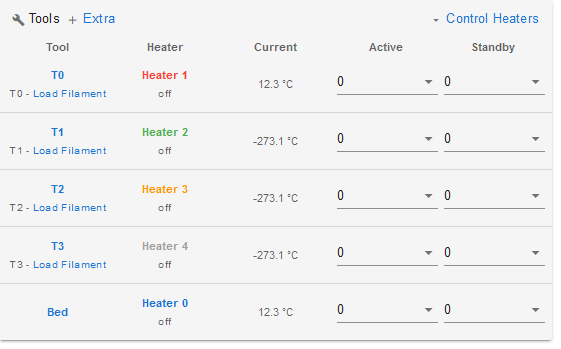
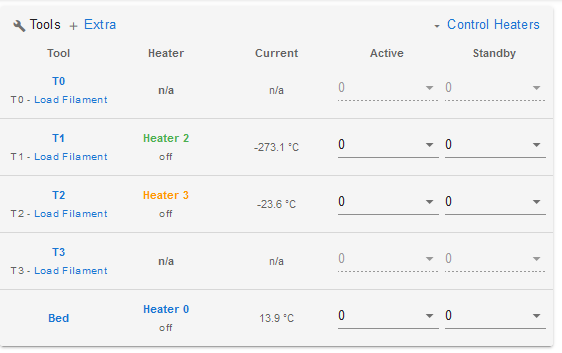
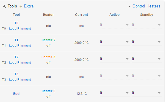
Thermistor 104nt-4-r025h42g
-
@Phaedrux said in Thermistor 104nt-4-r025h42g:
irmware for the wifi module didn't flash properly. You can usually resolve this by connecting via USB and using
M587: Failed to add SSID to remembered list: another SPI transfer is pending ist the original Error
M997: File 0:/firmware/DuetWiFiServer.bin not found is the Error.
What went wrong. Such a dictionary is not existing on the sd card.Just copied the files...now on the best way to 3.45
-
@MIke-1 said in Thermistor 104nt-4-r025h42g:
What went wrong. Such a dictionary is not existing on the sd card.
The 3.3 update adds a firmware directory. Either the directory creation failed or the firmware update looked there before it was created. Once you're passed 3.3 it's not an issue anymore.
-
Made it to 3.45 now

I finshed the configurator and now want to use this as a basis to build it all up.
The config is quite strange. I have issues with M950 and I think I mess up channels.
Here is a section for the Z-Probe:
; Z-Probe Configurator
;M558 P5 C"^zprobe.in" H5 F120 T18000 ; set Z probe type to switch and the dive height + speeds
;G31 P500 X0 Y0 Z2.5#########################################################
;New code: Duet website
;M558 P9 C"zprobe.in" H5 F120 T3000 ; BLTouch connected to Z probe IN pin, free up MOD pin
;M950 S0 C"zprobe.mod" ; servo/gpio 0 is Z probe MOD pin
;...
;M280 P0 S10 ; send control signal to BLTouch through servo/gpio 0old code
M558 P7 X0 Y0 Z2 H3 F360 I0 T20000 ; Set Z probe type to switch, the axes for which it is used and the dive height + speeds
G31 P200 X0 Y0 Z0 ; Set Z probe trigger value, offset and trigger height ; set Z probe trigger value, offset and trigger height
M557 X15:385 Y15:385 S40 ; define mesh grid####Toolchanger example:
M558 P8 C"io3.in" H3 F1000:300 I0 T30000 ; Set Z probe type to switch, the axes for which it is used and the dive height + speeds
G31 P200 X0 Y0 Z0 ; Set Z probe trigger value, offset and trigger height
M557 X-140:140 Y-80:80 S40 ; Define mesh gridHow do I detect which is the right channel?
-
This post is deleted! -
M950 uses pin names. You can learn about them here: https://docs.duet3d.com/User_manual/RepRapFirmware/Migration_RRF2_to_RRF3#pin-names
-
old code
M558 P7 X0 Y0 Z2 H3 F360 I0 T20000 ; Set Z probe type to switch, the axes for which it is used and the dive height + speeds
G31 P200 X0 Y0 Z0 ; Set Z probe trigger value, offset and trigger height ; set Z probe trigger value, offset and trigger height
M557 X15:385 Y15:385 S40 ; define mesh gridnew code
M558 P7 C"zstop" H3 F360 I0 T20000
G31 P200 X0 Y0 Z0 ; set Z probe type to switch and the dive height + speeds
M557 X15:385 Y15:385 S40Does this make sense? The cable is linked to the z-endstop on the board.
Is P7 the motor because ist should be P2 as it is linked to the barod's z-axis ?
-
No P is the probe type.
https://docs.duet3d.com/en/User_manual/Reference/Gcodes#m558-set-z-probe-type
-
-
@MIke-1 said in Thermistor 104nt-4-r025h42g:
But the last 3 termistiors do show -273°C
Can you show a screenshot of what you mean?
Can you send M98 P"config.g" in the gcode console and copy paste the results here?
-
@Phaedrux said in Thermistor 104nt-4-r025h42g:
M98 P"config.g"
M98 P"config.g"
HTTP is enabled on port 80
FTP is disabled
TELNET is disabled
Error: Unknown pin name 'fan3'
Error: Fan number 3 not found
Error: Unknown pin name 'fan4'
Error: Fan number 4 not found
Error: Unknown pin name 'fan5'
Error: Fan number 5 not found
Error: Unknown pin name 'fan6'
Error: Fan number 6 not found
Error: Unknown pin name 'fan7'
Error: Fan number 7 not found
Error: Unknown pin name 'fan8'
Error: Fan number 8 not found
Warning: Macro file config-override.g not found
Have to got to work now

-
If you get a temperature of -273°C, this indicates an open circuit, i.e. nothing is connected to the defined pins:
Check that the temperature sensor is connected to the correct pins
Check the wiring for breaks
Measure the resistance of the wires that connect to the Duet, and that it corresponds with what the firmware expects
Check that the configuration is set correctly for the temperature sensor. -
@MIke-1 said in Thermistor 104nt-4-r025h42g:
Error: Fan number 3 not found
Error: Unknown pin name 'fan4'
Error: Fan number 4 not found
Error: Unknown pin name 'fan5'
Error: Fan number 5 not found
Error: Unknown pin name 'fan6'
Error: Fan number 6 not found
Error: Unknown pin name 'fan7'
Error: Fan number 7 not found
Error: Unknown pin name 'fan8'
Error: Fan number 8 not foundFor the fan names you'll need to use the actual fan pin names of where they are connected. Such as duex.fan# etc
-
All fans except one are running
M98 P"config.g"
HTTP is enabled on port 80
FTP is disabled
TELNET is disabled
Error: Unknown pin name 'duex.fan0'
Error: Fan number 0 not found
Error: Unknown pin name 'duex.fan1'
Error: Fan number 1 not found
Error: Unknown pin name 'duex.fan2'
Error: Fan number 2 not found
Warning: Macro file config-override.g not foundNow I copied the old config-override.g into the directory and remevet duex. for the first 3 fans
M98 P"config.g"
HTTP is enabled on port 80
FTP is disabled
TELNET is disabled
Warning: Heater 0 predicted maximum temperature at full power is 403°C
Warning: Heater 1 predicted maximum temperature at full power is 715°C
Warning: Heater 2 predicted maximum temperature at full power is 842°C
Warning: Heater 3 predicted maximum temperature at full power is 494°C
Warning: Heater 4 predicted maximum temperature at full power is 575°C
Error: Heater 5 not found
Error: Heater 6 not found
Error: Heater 7 not foundShown temperatures are unchanged. What to do next?
-
@MIke-1 said in Thermistor 104nt-4-r025h42g:
Shown temperatures are unchanged. What to do next?
Did you see my previous reply?
If you get a temperature of -273°C, this indicates an open circuit, i.e. nothing is connected to the defined pins:
Check that the temperature sensor is connected to the correct pins
Check the wiring for breaks
Measure the resistance of the wires that connect to the Duet, and that it corresponds with what the firmware expects
Check that the configuration is set correctly for the temperature sensor. -
I have say thanks for great help!!! But somehow I am completely lost.
The old config worked except for the beforlast termistor (I changed it but should be OK)
Now I checked the wiring! 87d3ed42-0e46-4a99-b7dd-e0b7291af44d.jpg
What are these 2 small PCBs on top?
E0Temp
PCB lower
PCB upper
E3Temp 150Ohm
I think I did not get how it works...
Here is my old and new config
config.g -
Those look like PT100 daughterboards. If that's the case, those are not thermistors, but PT100 sensors, an your config needs to change.
https://docs.duet3d.com/en/Duet3D_hardware/Accessories/PT100_Temperature_Daughterboard
https://docs.duet3d.com/User_manual/Connecting_hardware/Temperature_connecting_PT100
-
I do have some severe mismatches with the pins, and it will take a while for me to understand this (coding), but wouldn't it make sense to remove the daughterboards?
-
@MIke-1 said in Thermistor 104nt-4-r025h42g:
wouldn't it make sense to remove the daughterboards?
No, then you would have to remove the PT100s as well and replace them with thermistors.
The coding part isn't very difficult, really. The only thing that needs to change is the M308 lines that describe the sensor setup to the firmware. Right now it's telling it it's a thermistor.
It would help to know exactly which sensor is connected where. I can't quite tell from your photo, but it looks like you have a resistor and a pair of wires connected to the bottom board, and 4 wires connected to one of the top. Can you verify what is connected where?
If nothing has physically changed hardware wise from when your previous config was used we can infer that channels X200, X202 and X203 were in use.
See if this section works
; Heaters M308 S0 P"bedtemp" Y"thermistor" T100000 B4138 ; configure sensor 0 as thermistor on pin bedtemp M950 H0 C"bedheat" T0 ; create bed heater output on bedheat and map it to sensor 0 M307 H0 B0 S1.00 ; disable bang-bang mode for the bed heater and set PWM limit M140 H0 ; map heated bed to heater 0 M143 H0 S120 ; set temperature limit for heater 0 to 120C ; Heater1 M308 S1 P"spi.cs0" Y"rtd-max31865" ; create sensor number 1 as a PT100 sensor in the first position on the Duet 2 daughterboard connector M950 H1 C"duex.e1heat" T1 ; create nozzle heater output on duex.e3heat and map it to sensor 1 M307 H1 B0 S1.00 ; disable bang-bang mode for heater and set PWM limit M143 H1 S280 ; set temperature limit for heater 1 to 280C ; Heater2 M308 S2 P"spi.cs3" Y"rtd-max31865" ; create sensor number 2 as a PT100 sensor in the second position on the Duet 2 daughterboard connector M950 H2 C"duex.e2heat" T2 ; create nozzle heater output on duex.e4heat and map it to sensor 2 M307 H2 B0 S1.00 ; disable bang-bang mode for heater and set PWM limit M143 H2 S280 ; set temperature limit for heater 2 to 280C ; Heater3 M308 S3 P"spi.cs4" Y"rtd-max31865" ; create sensor number 1 as a PT100 sensor in the first position on the Duet 2 daughterboard connector M950 H3 C"duex.e3heat" T3 ; create nozzle heater output on duex.e5heat and map it to sensor 3 M307 H3 B0 S1.00 ; disable bang-bang mode for heater and set PWM limit M143 H3 S280 ; set temperature limit for heater 3 to 280C ; Heater4 M308 S4 P"duex.e4temp" Y"thermistor" T100000 B4138 ; configure sensor 4 as thermistor on pin duex.e6temp M308 H4 C"duex.e4heat" T4 ; create nozzle heater output on duex.e6heat and map it to sensor 4 M307 H4 B0 S1.00 ; disable bang-bang mode for heater and set PWM limit M143 H4 S280 ; set temperature limit for heater 4 to 280C -
Unfortunately not much of a difference

This is the old setup wich worked except the 3rd thermistor.
; Heaters
M305 S"Bed" P0 T100000 B4138 C0 ; Set thermistor + ADC parameters for heater 0
M143 H0 S150 ; Set temperature limit for heater 0 to 150CM305 S"T0" P1 T100000 B4138 C0 ; Set thermistor + ADC parameters for heater 1
M143 H1 S350 ; Set temperature limit for heater 1 to 550CM305 S"T1" P2 T100000 B4138 C0 X200 ; Set thermistor + ADC parameters for heater 2
M143 H2 S350 ; Set temperature limit for heater 2 to 550CM305 S"T2" P3 T100000 B4138 C0 X200 X202 ; Set thermistor + ADC parameters for heater 3
M143 H3 S350 ; Set temperature limit for heater 3 to 550C
;I replaced it by one of these:
;https://de.aliexpress.com/item/1005002781227348.html?spm=a2g0o.cart.0.0.29b04ae4OVMoF9&mp=1&gatewayAdapt=glo2deu
;But it never worked and because of this i updated the firmwareM305 S"T3" P4 T100000 B4138 C0; X203 ; Set thermistor + ADC parameters for heater 4
M143 H4 S350 ; Set temperature limit for heater 4 to 550CH1 T0 is linked to with 2 cables to E0Temp
H2 T1 is linked to the bottom board with a resistor
H3 T2 is linked with 4 wires connected to one of the top
H4 T3 is linked with 2 cables to E5TempI will be away from my printer for I guess a week now...
-
@MIke-1 you response is confusing me, it looks like you have thermistors in your original confit but PT100 boards installed, one of the PT100 board has a resistor in it as a reference.
Please can you confirm which wire goes to what hotend and where its currently plugged in for all of the temperature sensors (except the bed as that looks like its working). Once you have that. measure the resistance across the sensors to see if they are 100K (thermistors) or 100R (PT100).