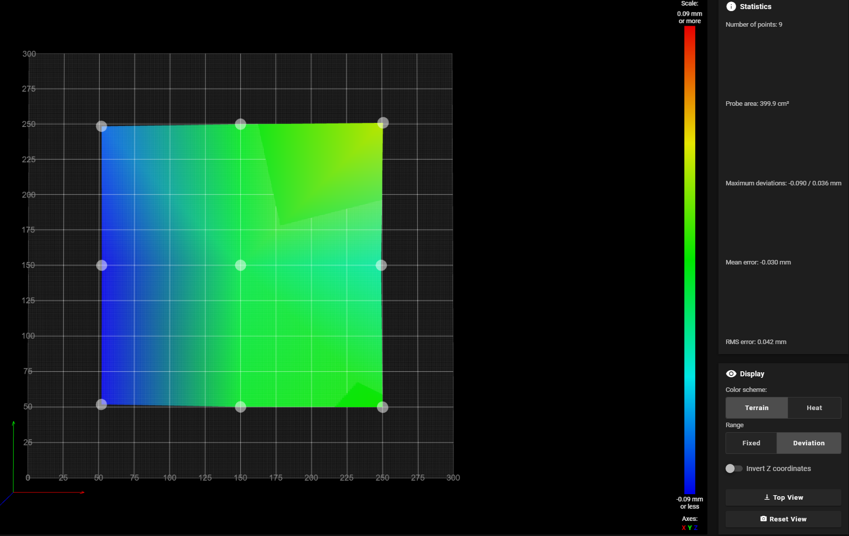
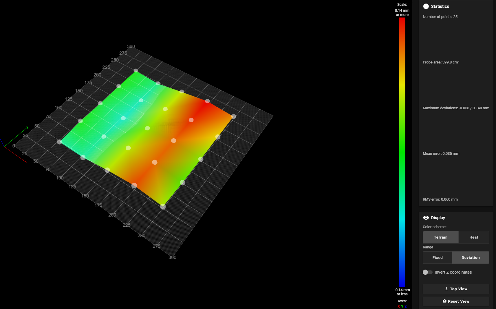
Mesh Compensation active but still uneven first layer
-
@adamfilip could anything stop the compensation from moving Z in negative? I assume even machine limits . are ignored
-
@adamfilip You could try allowing small negative movements to see if it makes any difference, but looking at your mesh, would any compensation require a movement below zero from say a 0.2mm layer height?
Some thoughts and suggestions on your problem....
Was the bed heated when you created the mesh? Could the shape of the bed (or any flex plate), be changing due to differences between probing and printing (like temperature)?
Are your probe offset settings correct? From your config.g it seems like the probe position is offset 39mm from the nozzle, but the comment next to the setting seems to say it is actually 16.4mm left and 29.27mm in front of the nozzle (which does not match the setting). If the probe offsets re wrong then the wrong part of the mesh will be being used to perform corrections.
The usual cause of problems like this seems to be due to a mechanical issue. This is particularly true when the probe is offset from the nozzle. When you have an offset like this then a small twist to the frame can result in the sort of issues you are seeing (because in effect the Z offset of the probe is different at different X/Y locations due to the twist). Another possible cause is that as the probe is moved around the bed then cables or other attachments to the probe/print head apply a force to the print head causing small movements (which get amplified by the probe offset).
You can check for the above by manually probing different points on the bed. Simply set up the bed the same way you did when creating the mesh (so heated up if you had heaters on when probing), make sure mesh compensation is turned off, then move the nozzle so that it is at the same location as one of your probe points lower the nozzle until it just touches a feeler gauge (or sheet of paper if you don't have a feeler gauge). make a note of the Z height and repeat at other points in the mesh. Then compare the heights obtained with the ones in your mesh file. If all is well they should match closely (with a constant offset that matches your gauge height). If you find that they vary over the bed then this probably indicates some sort of mechanical problem. This is best done with a nozzle without filament and that has been cleaned (to provide as "clean" a surface as possible when manually probing).
If you search the forum you may find other suggestions as this sort of issue seems to come up fairly often.
-
@gloomyandy Thanks for your reply
How would i allow a negative movement?
Bed was heated for 10min prior to doing a mesh
bed is very flat and stiff its using a 1/2" MIC6 Cast Alum bed + 1/16" FR4 Top Sheet thats held down on all sidesI would ignore some of the config.g comments, as they are not updated. the offset actual set is correct X0, X-39
Gantry has 4 motors that do tramming to bed, first (Like Voron)I have proper cable routing on my print head, so cables are not affecting the probe position as far as I can tell.
I have been searching this forum and also google searching to try and find an answer. ive tried dense meshes and grids with only 9 points (3x3) results are similar. Tried with no taper, with 3mm and with 10mm, same result.
Motion system and frame on my machine are quite ridgid, spent alot of time making this machine solid, id be surprised if it was a mechanical issue at this point.
-
@gloomyandy Here is a video to show how my machine is setup and how homing works on it
-
-

-
@adamfilip You allow a -ve movement by specifying a -ve value for the lower limit of Z in the M208 command. But if the maximum -ve value in your mesh is less than your first layer height (say 0.2mm), then mesh compensation will not need to move below Z=0, so even if the firmware was limiting the -ve movement it should not be an issue. If you do allow movement below Z=0 then take care because that may allow the nozzle to hit the bed.
I'm sure your machine is well built, but it only takes a very small twist to cause problems. I'd really recommend trying the test I have described above. It will allow you to get a better feel for how your printer is working and the shape of the bed. It is tedious but usually worth the effort.
Have you tried printing with the mesh disabled? That will also give you a good idea of the actual shape of the bed (as seen by the nozzle) and would also be a good way to check how well the probing you have matches the actual bed shape.
Your mesh seems to show a ripple, if you rotate the FR4 surface through 90 degrees does the ripple change with it?
One final point, I'd strongly recommend homing Z such that the X/Y position of the probe matches exactly one of your probe points. If you do that, then the selected point should always be very close to 0 in the mesh. Having a point like this allows you to do a quick sanity check on the mesh, to ensure that nothing "odd" is happening with it.
-
@gloomyandy I did three tests
genered 3 new meshes using ProbeAlum Bed with FR4 Sheet

Alum Bed with FR4 Sheet turned 90 degrees counter clockwise

Alum Bed without FR4 Sheet

-
@adamfilip
Basically the same image, although the print bed has been rotated.
If you have a straightedge, check your x-axis.
It looks like it is not straight but has a wave.Google Translate
--- Original Text ---Im Grunde genommen das gleiche Bild, obwohl das Druckbett gedreht wurde.
Wenn Du ein Haarlineal hast, dann prüfe mal Deine X-Achse.
Es sieht so aus als wäre sie nicht gerade sondern hat eine Welle. -
@adamfilip said in Mesh Compensation active but still uneven first layer:
M558 K0
You only have a single probe, so remove the K0. When you change settings in your other macros you don't include K0 to target the probe so some settings may be getting reset or misapplied.
So either remove the K0, or use it consistently and re-create your mesh.
-
I dont see how it would be possible for the X or Y axis to not be straight, using 20x20 Vslot alum extrusion, and using Exoslide Carriages, the motion is smooth, it would bind if it has a bend in it. extrusion is generally super straight. I really dont think this is the issues here
-
@adamfilip
If you turned the FR4 plate by 90° and the mesh looks almost the same, then it can only be because of the X-axis.
A mirror is generally one of the flattest surfaces, if you have a mirror the size of your print bed then create a mesh with it.
If it looks the same as the previous meshes, then the aluminum profile must have a wave.While it won't have anything to do with the apparently flipped heightmap, it does explain the almost identical meshes of the three measurements you took.
Google Translate
--- Original Text ---Wenn Du die FR4 Platte um 90° gedreht hast und das Mesh sieht fast gleich aus, dann kann es ja nur an der X-Achse liegen.
Ein Spiegel ist im allgemeinen eines der ebensten Oberflächen, wenn Du einen Spiegel in der Größe Deines Druckbettes hast, dann erstelle damit mal ein Mesh.
Sollte es gleich aussehen wie die vorherigen Meshes, dann muss das Alu-Profil eine Welle haben.Es wird zwar nichts mit der anscheinend umgedrehten Heightmap zutun haben, aber es erklärt die fast identischen Meshes der drei Messungen die Du gemacht hast.
-
@norder When I choose a homiung point that represented the lowest point on the bed. so it didnt go into negatives when I did the mesh levelling, it worked fine.
choosing a homing point thats higher than the lowest point, seems to be messing up mesh compensation.
-
@adamfilip said in Mesh Compensation active but still uneven first layer:
choosing a homing point thats higher than the lowest point, seems to be messing up mesh compensation.
The points are relative to the Z0 point and it can go below the zero point no problem.
-
@phaedrux But yet it wasnt.

