Query Mesh Bed Compensation Status
-
Hi! Is it possible to query whether or not mesh bed compensation is currently in use? DWC says that it is, but I can see that my nozzle is at different heights as I print my skirt.
Perhaps I'm doing something wrong?
I have a Modix Big-60, with a 600 x 600 mm build volume. I first perform the bed leveling operation (which homes xyz, does a z probe, then measures at each of the 4 corners repeatedly until the bed is level to within 0.02 mm, then does a z probe again), then I perform a 100-point map. When I start my print, though, like I mentioned, I can clearly see a difference between the layer heights on the corner near the z-zero probe and the opposite corner.
Should I be doing something differently?
-
@tfjield said in Query Mesh Bed Compensation Status:
I have a Modix Big-60, with a 600 x 600 mm build volume. I first perform the bed leveling operation (which homes xyz, does a z probe, then measures at each of the 4 corners repeatedly until the bed is level to within 0.02 mm, then does a z probe again), then I perform a 100-point map.
Should I be doing something differently?
Leveling by measuring at the corners can yield less that optimum results.
Try measuring at the centers of the sides.
Then when you are happy with the results run a 4 point height map to see if you gantry is moving parallel to the bed surface.
If the height map does not come out nice and level the frame members supporting the gantry need adjustment.
Here is a good video showing what you should perhaps try:
Given the size of your printer you are going to have issues with Mesh Bed Compensation. Even at the max number of points (21 x 21) you are talking some 30mm between points. That leaves a lot of room for bed irregularities to hide.
So create the height map using the max points (21 x 21). This is most easily done with the P parameter of the M557.
The next step would be find someone to make you a bed as flat as reasonable.
What is you bed currently made of?
Frederick
-
@tfjield m122 will report the comp in uses as either 'mesh' or 'none'
-
@fcwilt Hey, first, I just wanted to say thank you for all the effort you put into supporting people on this forum. I really appreciate it. This is my first time using Duet boards, and they're awesome!
I'll dig into that video, but first a few questions to help my understanding:
- If my bed is being leveled the same way every time, what difference would it make where I perform the leveling?
- Theoretically, if the map is good then wherever the map points were taken I should be spot on, right? So in my case, with 600 mm in each direction I should only see issues within the ~67 x ~67 mm squares, right?
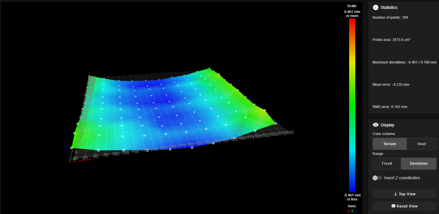
Here's my height map:

If I look at the 4 corners where the bed leveling took place, I see z values of 0.016, 0.022, 0.016, and 0.043, which looks pretty good to me.
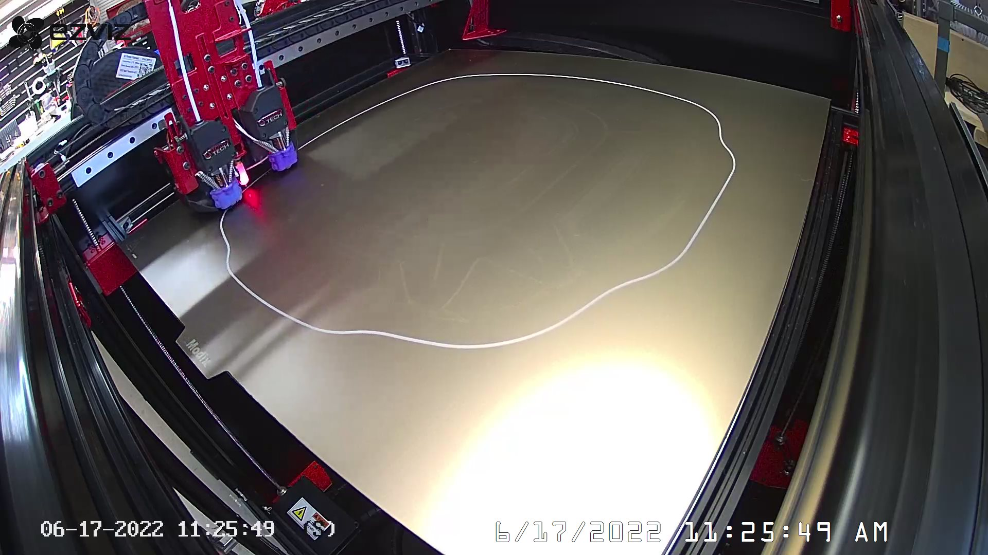
So given the saddle shape of the bed, I would think that if I were going to have any issues it would be in the center, where there's maximum deviation. But instead, looking at the width of my skirt lines, it looks like I'm the right height near the origin and gradually too high as I move diagonally to the other corner.
I was watching very closely when I started my print. I know you can't see anything in this image, but the top left was perfect, top right and bottom left pretty good, and bottom right the worst (too high).

It also shows on the inside of part when it prints the first layer.
Per Modix, my bed is "6.35mm thick, Alcoa Mic6 milled cast aluminum plate," and I have the magnetic bed on it with PEI on spring steel. I don't know who makes the magnetic bed for Modix. I perform the height map when it's warmed up, and it's very consistent from map to map.
-
Always glad to help when I can - or at the very least not make things much worse.

The areas between the points are where you would expect to find problems.
As to understanding the leveling issues watch the video. It should make it all clear.
Are you setting the Z=0 Datum (a single G30) at the center of the bed?
The colors of your height map suggest you are not.
Does the bed have any adjustments allowing to raise/lower different places on the bed.
Assuming the gantry is nice and square to the bed it looks like the bed is sagging quite a bit.
Frederick
-
Some other fun reasons why a mesh bed may not be in line with reality:
a) skewed probe
b) gantry twistSince the heightmap is a CSV file you could for tests modify one of the points to be 10mm higher and then after loading the height map, make a move that crosses or ends at that modified point. It should move the bed 10mm lower.
I like @fcwilt s idea to probe Z at the center of the bed, but I like it even more when the Z probe is close to the center of the bed and matches one of the points in the mesh. That gives you good reference between probing Z and building the mesh.
-
Also
echo move.compensation.typereturns "none" when compensation is disabled, and "mesh" when a mesh is loaded. -
@oliof said in Query Mesh Bed Compensation Status:
I like @fcwilt s idea to probe Z at the center of the bed, but I like it even more when the Z probe is close to the center of the bed and matches one of the points in the mesh.
Absolutely the preferred approach.
I don't do it because I create a number of different height maps for different printing situations.
Frederick
-
No, my Z=0 Datum isn't in the center, it's at the nearest corner near the origin. (One of the 4 corners that's probed during the bed leveling.) And I'm going to watch the video now, because I don't understand why it makes any difference where my datum is, as long as it's in the same spot before and after height mapping...
No, no bed adjustments other than the motors.
And yes, that sag seems pretty typical for these machines, from what I've seen from others' heightmaps.
@oliof I think the probe looks fine, but I'll double-check the gantry to see if I have any twist.
So thinking about putting the z datum at the center of the bed... In my case that would be near one of the lowest points on the bed. So if I were to print something with the mesh compensation turned off, the first thing I would probably do is scrape my nozzle through the PEI surface... Wouldn't it be safest to have the datum at the highest point of the bed, so that if, somehow, mesh compensation were turned off then the failure would be to print too high?
And I'm convinced now that mesh compensation IS turned on. The z axes motors move a little as the printhead rounds the bed. I think it would be a lot worse if it weren't. It's just something that's off...
-
OK, I spent this weekend calibrating and tuning and learning RRF, and I made a lot of progress!
Turns out my problem was a twisted y-axis. It was pretty square on the front but twisted quite a bit on the back. As my probe offset in the x-axis is 24 mm, even a couple of degrees would result in a significant layer height error. Fixing this problem was the key.
But beyond that, I changed quite of the logic around the bed leveling.
My bed has the typical "Modix sag" because it is not supported with rigid-enough members. The front and rear rails are 2020 extrusion spanning ~80 cm, and that's just not stiff enough. I have 2040 on order, and I'm going to upgrade these when it arrives. It won't eliminate the sage, but should improve it significantly.
It also sags front to back, as there is no support on the sides, but my guess is that's intentional: The y-axis gantry sags, too and as a result, you can barely see it in the surface maps! I'll deal with this at a later date...
I watched the video, but it wasn't very useful for my situation. My bed is supported on the 4 corners, not just 3 points, and while I can't make the midpoints of the 4 edges coplanar, I can make the corners coplanar.
So I put my z datum at the front left corner, because this is one of the highest spots. If mesh bed compensation is turned off for some reason, the failure mode will be printing too high rather than engraving into my PEI sheet. (And I keep finding new macros that turn mesh bed compensation off!
 I think I've fixed all that, now, so I shouldn't be surprised and I'm not rehoming all the dang time!)
I modified the routines so that:
- The z homing routine is at the datum location,
- The 4-corner leveling routine uses the same location for one of the corners,
- The mesh bed compensation is performed between the 4 corners used for bed leveling. and
- The probe z height compensation is performed at the same location.
As a result, the height map reads zero at the 4 corners, which includes my datum.
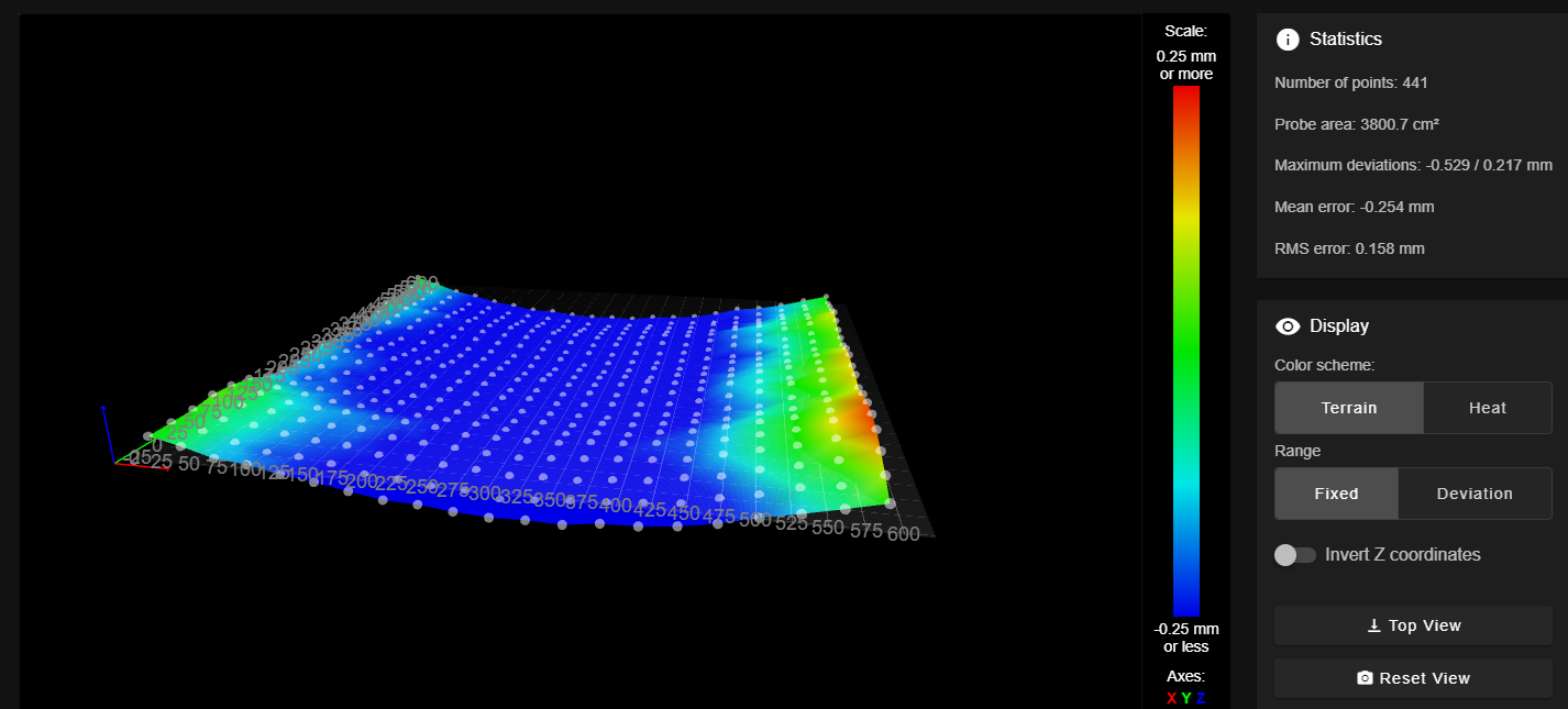
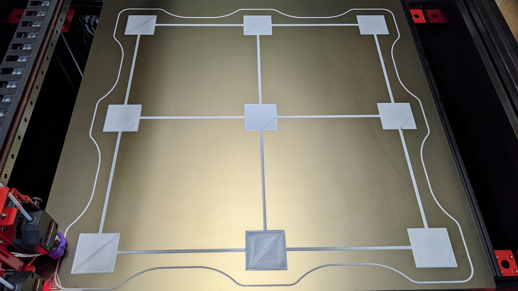
I've performed the height mapping with a 21 x 21 grid, and my first layer tests are looking amazing, now! Now on to fine tuning my slicer settings...
Thank you for all your help!!
And a pretty pictures:


-
That looks very good.
Any reason you could not add a frame member, running front to back, at the center of the bed, to get rid of that sag?
The flatter the bed the less work the Z axis has to do during printing, saving wear and tear.
Frederick
-
@fcwilt Thank you!
Yes, I can add frame members from front to back. There are already two members there, but they're not under the edges of the bed. (You can see one of them on the right in the image above. Just to the right of the actual bed. That's how they tell us to put it together.) My guess is that they originally were under the bed, but now they have us put them off to the side so that the bed sag compensates for the y-axis sag. (The y-axis also runs front to back.)
I've read a few posts about people stiffening up the y-axis, and if I do that, then I'll add the support members for the bed, as well.

-
@tfjield said in Query Mesh Bed Compensation Status:
...off to the side so that the bed sag compensates for the y-axis sag.
That does not strike me as a good design philosophy - create one flaw to compensate for another.

So I would be in the "fix the sag in both Y and the bed" crowd.
Good luck.
Frederick
-
@fcwilt Yup, I'm with you! It's just triage right now in the little time I have between prints!
