Adventures into input shaping and PA!
-
Hello there!
I finally got around to working with input shaper and pressure advance this weekend with my duet 2 wifi modded CR10s, and I wanted to share my results for anyone that is interested in working on this. I also wanted to see if anyone can spot anything I've done wrong with my analysis. I first dialed in pressure advance, and I know I'll need to recalibrate this once I added the frequency cancellation to my slicer.
First up, Pressure advance: I'm running a direct drive Hemera, and followed Chris's tutorial to figure out the right number. These were printed at 40mm/s with accelerations at 800mm/s and jerk of 10. I've got it turned way down as after putting on the hemera as I'm really struggling with ghosting, hence the input shaping. https://www.youtube.com/watch?v=LhYJruVdpxk
I ended up choosing a number around .04 with PLA. I think it was the best balance between losing corner accuracy and reducing the seem bulge. Funny enough, it looks like my system naturally bulges too much at the seem, and then takes a second to get material flowing again, which leaves a gap as the next layer starts. Going through this tuning helped get a much more complete seem, and helped with pillow casing on the corners.
based on recommendations, it seems like my system may be a running a bit high on the M572 value for a direct drive hemera, any thoughts on that?
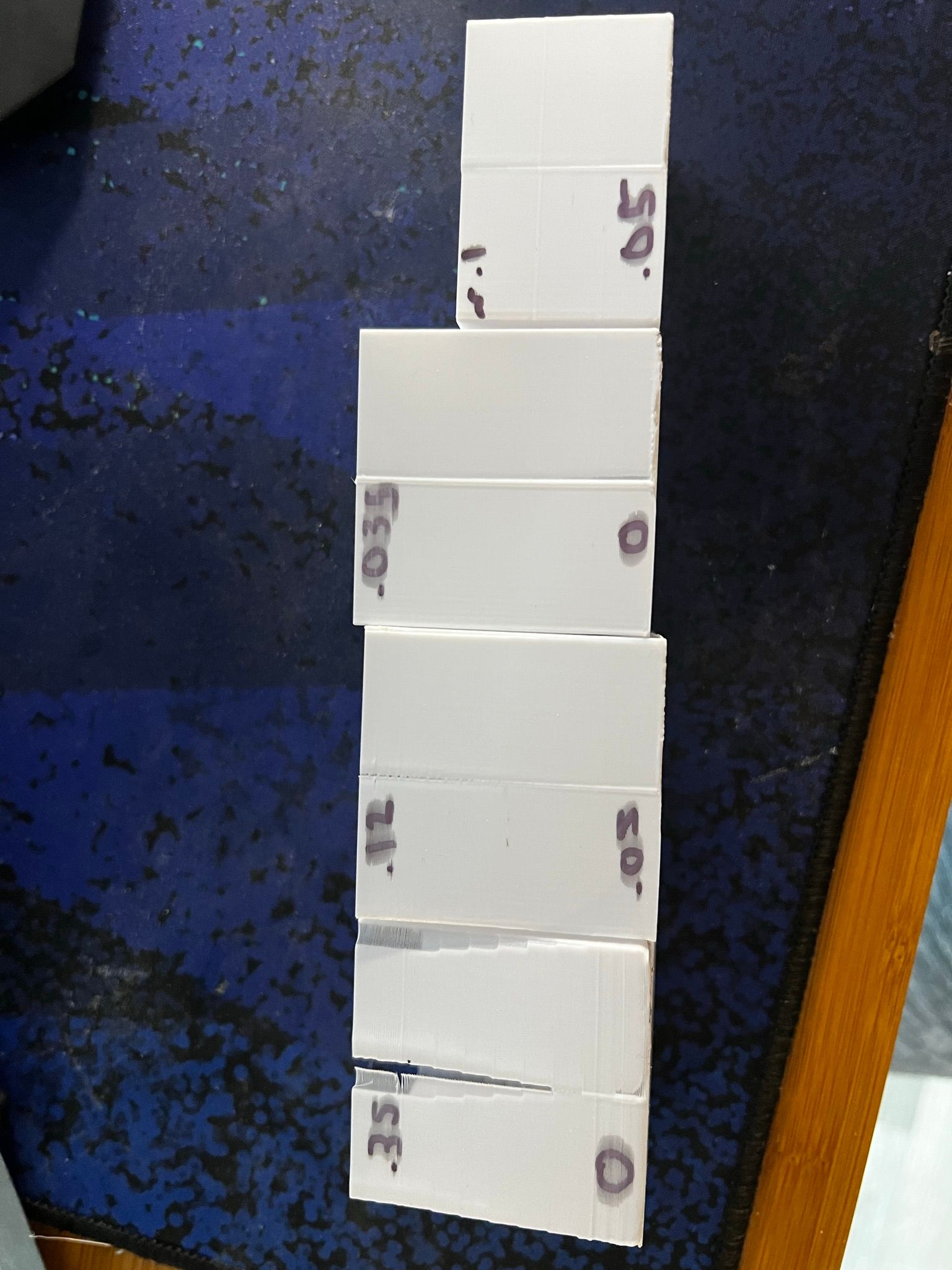
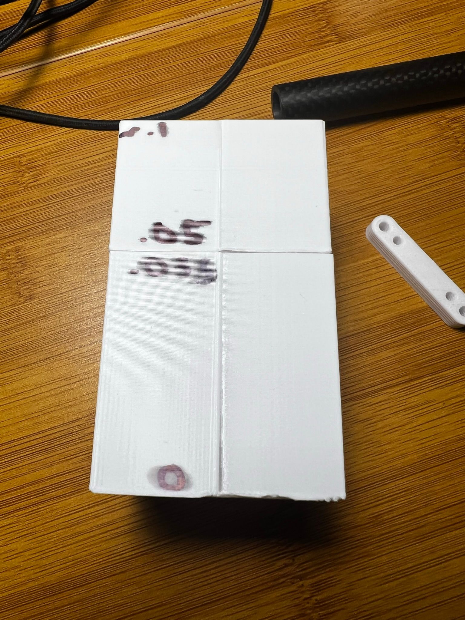
onto input shaper,
I supposedly bought a LIS3DSH chip from amazon to work with which has LIS3DH written on the PCB, but reports back as the S version, so I'm going to run with that it's the S version
 I mounted the chip some of the leftover mounts on the hemera stepper after making a quick bracket. I believe this would be I50 orientation, but more on that in a second. I followed the direct wiring into the thermocouple expansion like the picture I copied in here:
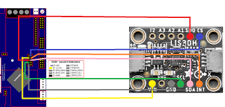
The pinout is a bit different for this chip layout in the picture, but is fairly straight forward to map. I used a basic ribbon cable about 20in long which is made up of two segments of cable and had no issues with it working, and the collected data looks fairly clean too. So for Duet 2 users it looks like there isn't much to worry about with grounding and interference.
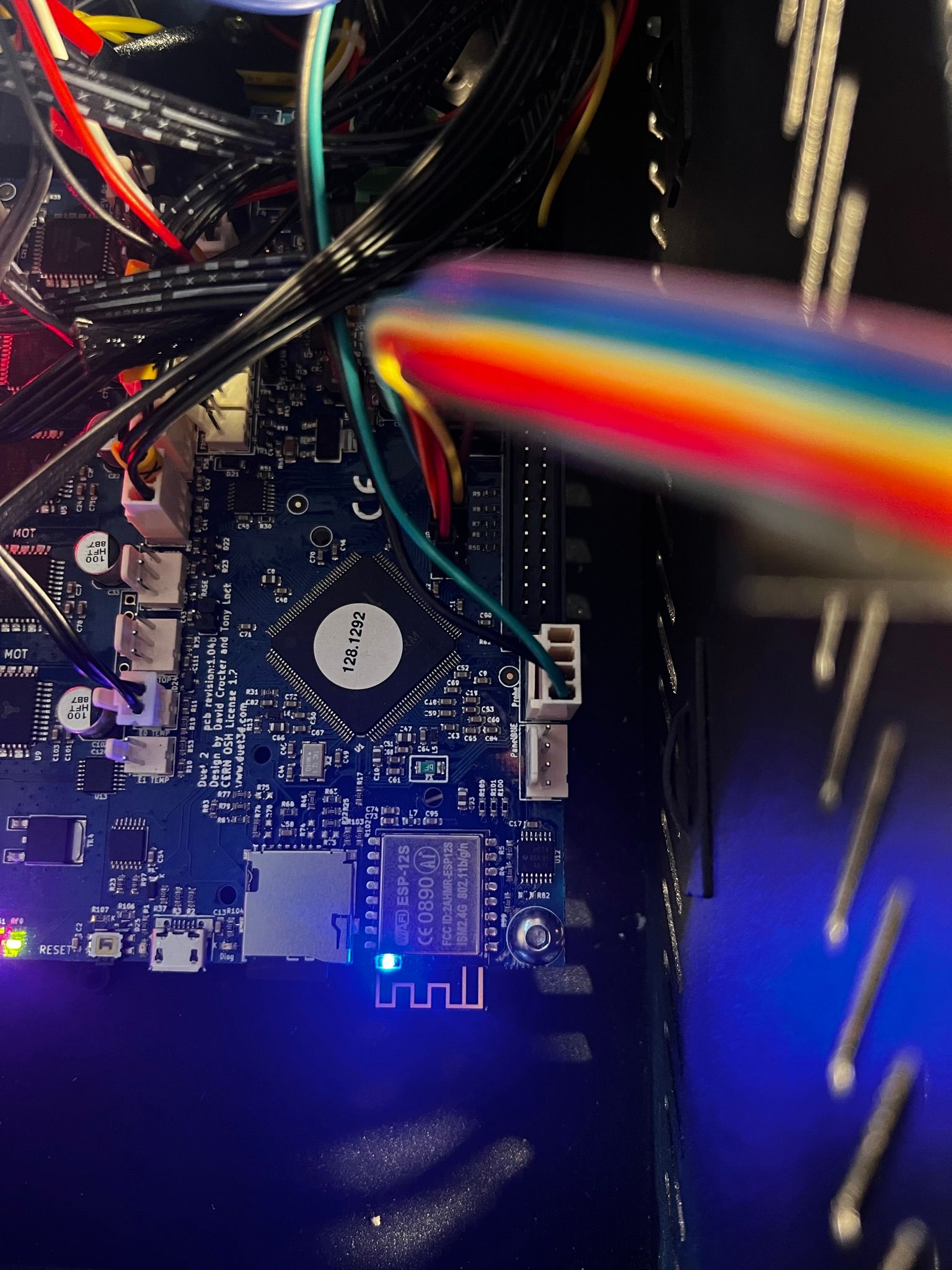
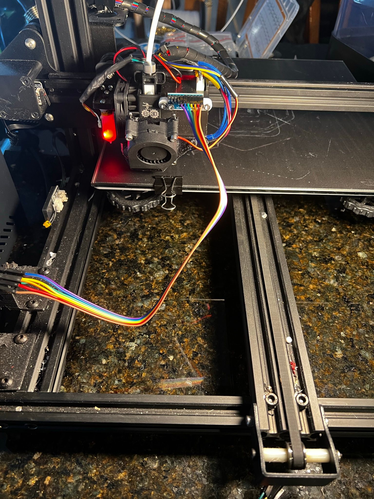
Otherwise I setup the accelerometer as prescribed in duet documentation, and it all worked great! I also used the script to jog the system and capture the resonance data on the tool head. I played around with the feedrate from F6000 to F20000 and didn't see a lot of difference, though my 800mm/s2 acceleration is probably capping out over a 50mm move. below is the raw data and the Fourier transform (both standard and wide band):
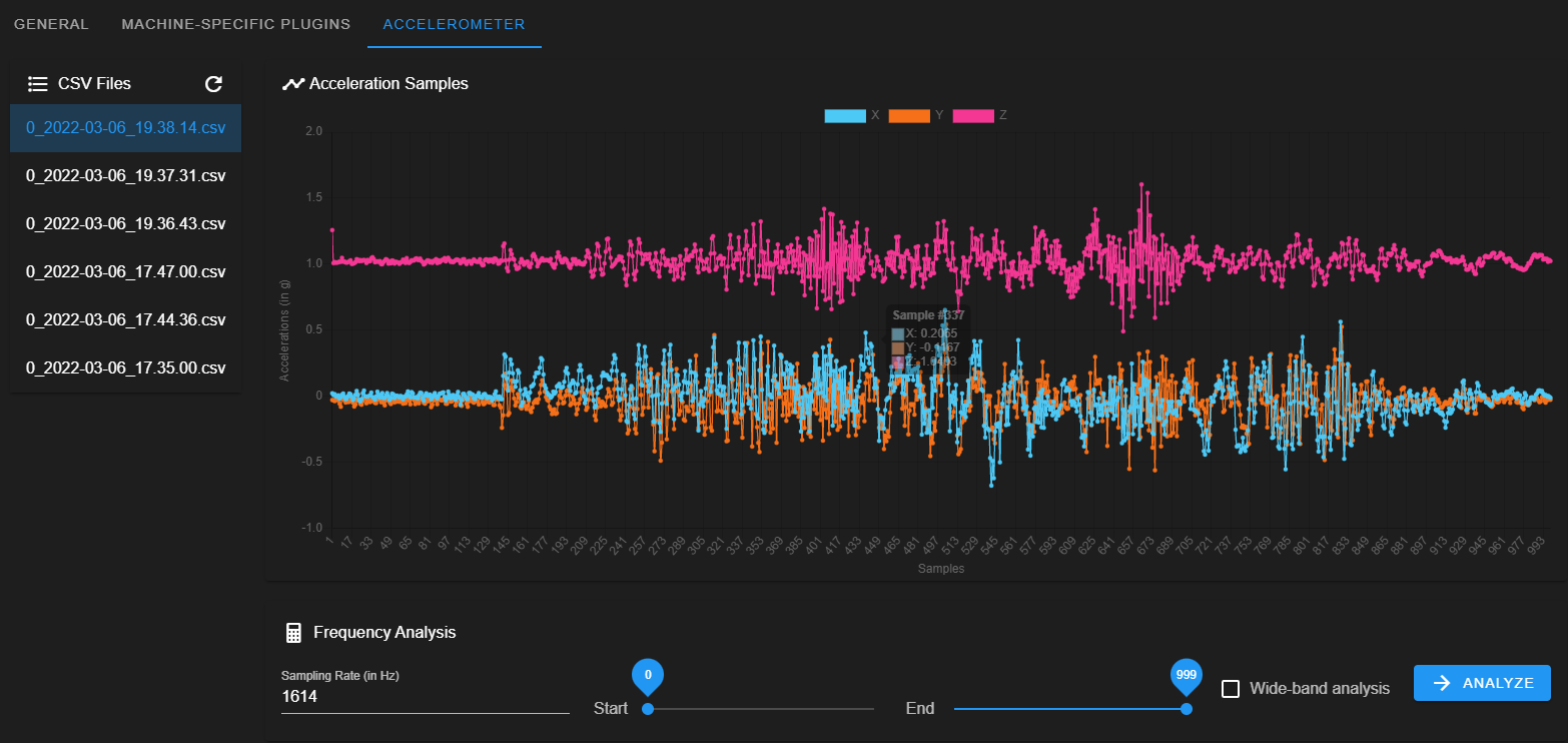
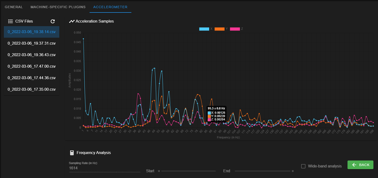
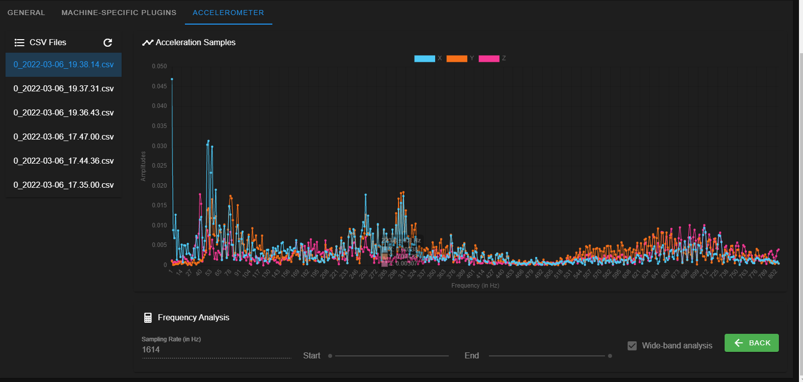
I'm going to ignore the peak at 1Hz, but it looks like I've got a double peak around 48-55Hz that could use cancelling and maybe at 80 Hz as well. it looks like there's something at 310Hz, but that's getting to be relatively high. It's been a long time since I've taken system dynamics and robotics, so I'm looking for a bit of guidance here. Is there a cheat sheet on what's good, bad, in between or other recommendations? I think I've got the orientation correct as Z is averaging around 1g acceleration - good to see the gravity is still working
 It seems like a lot of machines have a peak around 40 - 50Hz and then a second bump around 80Hz-ish, so my results seem reasonable.
As for what to do with this data, it looks like M593 works on all axes with reprap firmware. I've been watching a bunch of videos from guys running klipper, and they will apply specific tuning parameters per axes, am I understanding this correctly? I've only run tests with the accelerometer on the tool head / X axis, I need to connect it to the bed and run it some tests for the Y axis as well. I tried jogging the Y axis while the accelerometer was on the tool head and saw the 80Hz peak, so that's good that the tool head sees the same resonant frequency from the Y axis moving.
my next test is running a ringing tower print with the 52Hz and 80Hz cancelled with an EI2 (I saw a few folks recommended this shaper so we'll start with that) while varying the acceleration every 5mm with an M204 code. I'm trying 500 - 2250mm/s2 to start. I'll follow up with results from this test once the print is done!
-
First question,
how do structure the M593 code to cancel multiple frequencies? I tried:
M593 P"EI2" F52 ; input shaping test 3/7/2022
M593 P"EI2" F80 ; input shaping test 3/7/2022but only the second line of code stuck as the printer only reported the EI2 for 80Hz when I sent a M593 code. Do I need to use the colon syntax to list multiple frequencies?
-
@michaelr123 you can only have one frequency at a time.
my approach has been to use the input shaper plugin to work out which algorithm gives the flattest graph -
good to know. So you're just looking to deal with you're worst resonant frequency.
With that in mind, it sounds like what I should do is play with accelerations, speeds, and shapers with the accelerometer taking measurements to fiddle with it until I get the smoothest graph, is that correct?
From there I'm guessing you print a ringing tower to test the settings and go from there?
-
@michaelr123 said in Adventures into input shaping and PA!:
So you're just looking to deal with you're worst resonant frequency.
The more advanced input shapers work over quite a wide frequency range, so you can cancel a wide band of frequencies. For example, EI3 works over a 3:1 frequency range. See https://docs.google.com/spreadsheets/d/1R23r0KRFosGNWJEqsnCXL6ylpuayGqDvm8ocOszalV4. Predictive graphs like this will be incorporated into the input shaping plugin soon.
The problem with applying different shaping to different axes is that it results in wiggly rounded corners.
-
@dc42 very cool! I'm excited to see this come through!
So really these shapers are different styles of band-stop filters. One cool idea would be to design feet pads or connection points that mechanically dampen tuned frequencies. I've got "theory of vibrations with applications" sitting on my bookshelf that I never got around to. Maybe the next time I'm looking for some light reading I could crack into it
 Now that I have an accelerometer, I can check for resonant frequencies all over the machine and then design tuned spring-mass-damper components to mechanically dampen it.
I'll try a couple of different shapes and frequency combinations and see what I like. The results from the print are looking excellent at the moment even at double the frequency I've been printing at lately!!
one thing I'm curious/concerned about is this bracket that I bought as a retrofit for the CR10s and the hemera. This is the bracket I got:
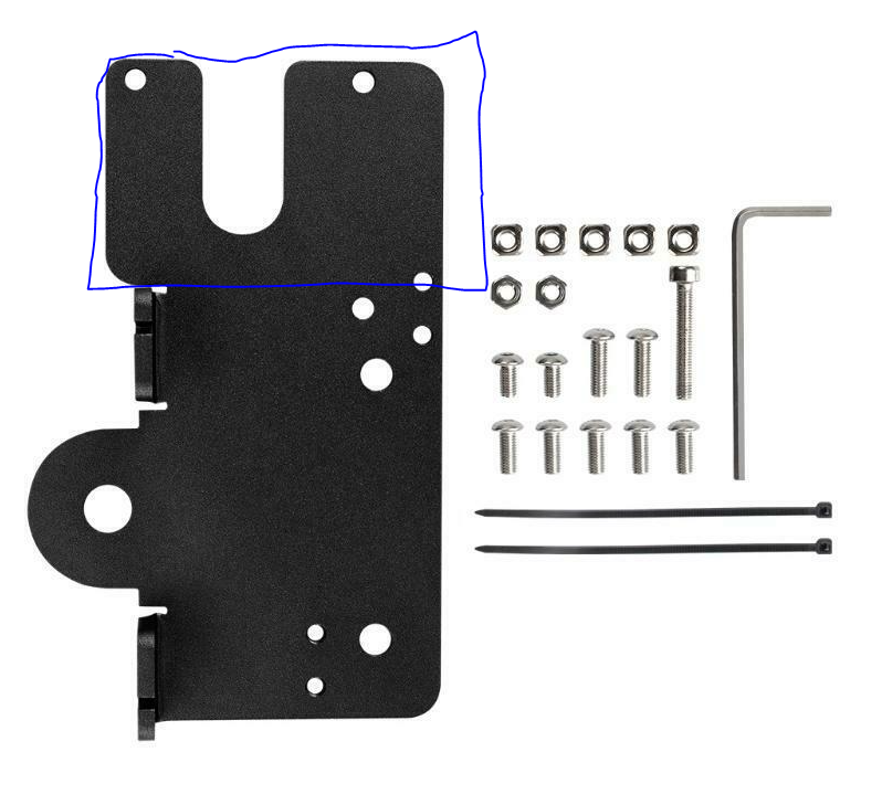
It adapts the the system so with just a thin printed plastic plate to stand off the assembly above the bolt heads for the V-wheels. The thing I don't like about it is that it suspends the hemera extruder out on a thin plate with 3 bolts marked in blue. just playing with it seems a bit tuning-forky. The first plate I printed was made of taulman 910, but I was seeing really bad resonance, so I tried replacing it with a TPU piece instead which seemed to help a bit. My next idea is to measure the results with both materials and see which has the better response.
-
Wow am I impressed how much of a difference this made! I was able to push my accelerations from 800 to 8000 and 6000 for X/Y respectively! The only thing holding me back is the Y axis losing steps at 8000. I turned up the current a bit and left the Y axis at 6000 after that. I also increased my my print speed to ~120mm/s with great results!
I ended up using the EI3 shaper with a S.025 modifier at 38Hz. This seemed to catch everything that was going on around the 25 - 55Hz mark.
I think the next thing I can try bumping up is the jerk settings. I'm still noticing some moves seem a little skate-y like a lower acceleration. This seems to be on smaller moves like the infill layers on benchy, but I'm still pretty happy with a ~35min benchy without even trying
 for a 12v CR10s, I think that's pretty damn good!
 -
I made a macro to speed things up. This is script I wrote:
M204 P10000 T10000 ; set acceleration
M593 P"EI3" S.025 F38 ; input shaping test 3/7/2022 change this as needed
G1 X-100 G4 S2 M956 P0 S1000 A0 G4 P10 G1 X100 F20000 ;movement code along X axis, collect data from accelerometerOne thing to remember as you're playing with accelerations, I think you need to update the M201 code in your config file to allow for an acceleration this high.