How to check the real current of the stepper motor
-
@zapta
M1000 requested measures 0.8379A with you new script -
@zapta
ive deleted the macro that contained
; Move slowly to identify peak stepper current.
; Assuming XY are already homed.G90 ; absolute positioning
G1 X100, Y100 ; starting pointG91 ; relative positioning
while iterations < 500
echo "Iteration " ^ {iterations}
;G1 X0.001 Y0.001 ; for cartesian printer
G1 X0.001 ; for core XY printer
G4 P250 ; Wait 250msG90 ; absolute positioning
but it is still continuously running , where would it be hiding so i can stop it

-
@moth4017 said in How to check the real current of the stepper motor:
but it is still continuously running , where would it be hiding so i can stop it
It should stop after a minute or two. What I do is pressing on the red STOP button on PanelDue or DWC to reset the machine. This also resets any configuration changes the script may do.
-
@moth4017 said in How to check the real current of the stepper motor:
M1000 requested measures 0.8379A with you new script
I guess it's now a question to the Duet team, is this a reliable measurement and is the result within the expected range.
-
@zapta I would expect it to be closer than that, it should be less than 10% out.
-
@dc42 so where does this leave us? is it lower that it should be or within acceptable parameter's

-
@moth4017 i tried the current measure on the extruder not using the script but setting the extrude speed to 0.001mm/s the highest reading i got was 0.1347A
m906
Motor current (mA) - X:1000, Y:1000, Z:600, E:1200, idle factor 30%
PM M913
Motor current % of normal - X:100, Y:100, Z:100, E:100 -
@moth4017, as reported in a previous post, I got X current that seems to be in range so I am trying to identify differences from your configuration.
-
I was measuring an X current on a motor that is connected to the daughter board. [theoretically it should behave exactly like a main board driver since it has direct connection]
-
This is by firmware configuration. It's an older firmware version than yours.
RepRapFirmware for Duet 3 Mini 5+ version 3.4.0beta5 (2021-10-12 13:53:24) running on Duet 3 Mini5plus WiFi (standalone mode)
Board ID: A0L0Y-5296U-D65J0-40KMN-0W03Z-HBTQS- [long shot in the dark] The Mini 5 uses on board current sense resistors so theoretically if the value is in connect or a connection is not good, it may increase the actual current without the drive being aware of it.
Not sure if it helps.

-
-
@zapta i notie there is a vref on the tmc do you know if this value changes when controlled by the miro ,
-
@moth4017, I am not an expert, but you can try searching the driver's datasheet for 'vref' and 'sense' and see if it helps. It's a smart chip so there are all kind of programming options for the RRF firmware to use.
https://www.trinamic.com/fileadmin/assets/Products/ICs_Documents/TMC2209_Datasheet_V103.pdf
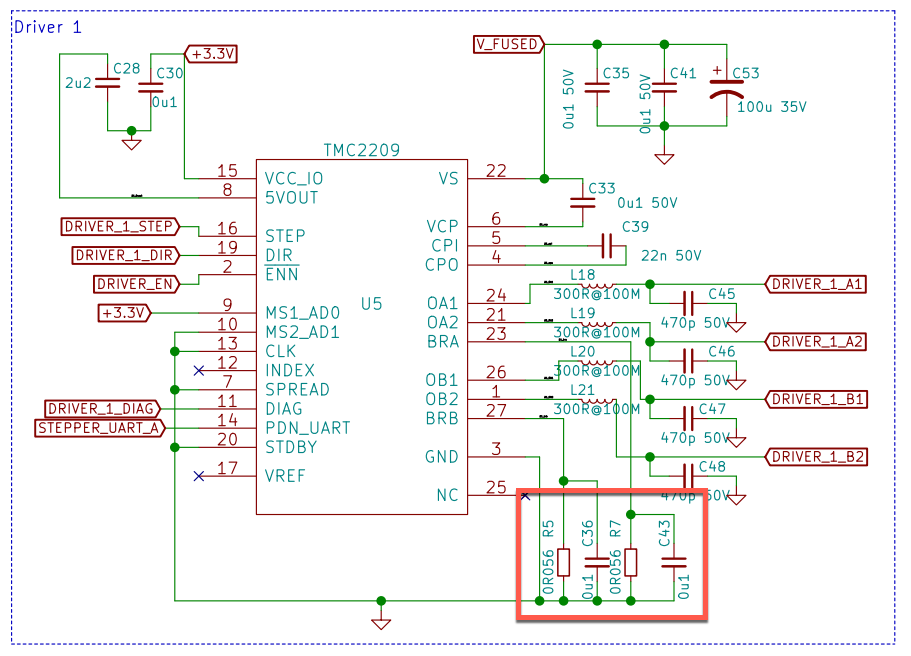
The schematic of the Mini 5 suggests that it uses 56 milliohms resistors for sensing the coil currents.

-
@zapta correct, the sense resistor is 0.056 ohms.
There are a few factors that may cause the current to be inaccurate:
- The internal resistance of the BRA and BRB pins needs to be taken into account. We assume this is 0.02 ohms, as specified on the datasheet.
- The driver reference voltage has a tolerance of +/- 5%
- The current will be rounded to the nearest multiple of approx. 74mA, usually down (up only if the next multiple is really close). This means that if you set 1000mA then the current setting requested from the driver will be 962mA.
-
@dc42 My BRA andBRB are 0.056ohms