G53 vs G54 issue
-
@baird1fa bring up your browser console and see if you are getting any errors. Share them here if you would please.
-
Nope, no errors when I run the config.g file or boot it up.

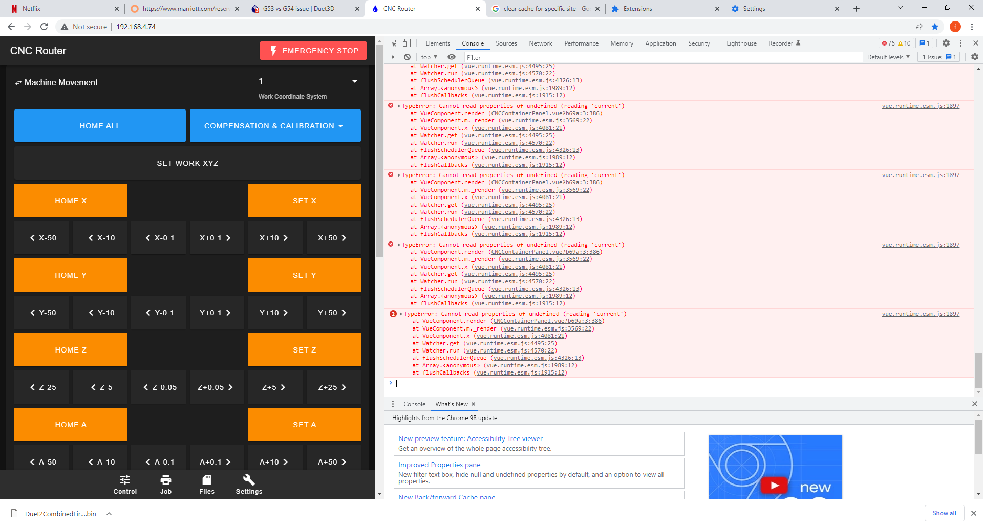
If I remove the M453 so it is in 3D printer mode then I get the DRO portion. But in the M453 CNC version the DRO is gone. I have also tried to move the M453 to different places in the config.g and that doesn't help either.
I even tried to let it boot up as a 3D printer then send the M453 command to put it in CNC mode and the DRO portion just disappears. Is it a bug maybe to do with the fact that I'm not using any of the built in drivers? I'm only using external stepper drivers. Could that have something to do with it?
Here is my config.g if that helps.
; Configuration file for Duet WiFi (firmware version 3) ; executed by the firmware on start-up ; ; generated by RepRapFirmware Configuration Tool v3.3.0 on Thu Aug 19 2021 13:14:05 GMT-0600 (Central Standard Time) ; General preferences G90 ; send absolute coordinates... M83 ; ...but relative extruder moves M550 P"CNC Router" ; set printer name ;M453 ; Make CNC board ; Network M552 S1 ; enable network M586 P0 S1 ; enable HTTP M586 P1 S0 ; disable FTP M586 P2 S0 ; disable Telnet ; External Drives M569 P5 S0 R1 T5:2.5:5:7.5 ; external drive 5 goes forwards requires an active high enable, 5us minimum step pulse, 2.5us minimum step interval, 5us DIR setup, and 7.5us hold time M569 P6 S1 R1 T5:2.5:5:7.5 ; external drive 6 goes forwards requires an active high enable, 5us minimum step pulse, 2.5us minimum step interval, 5us DIR setup, and 7.5us hold time M569 P7 S1 R1 T5:2.5:5:7.5 ; external drive 7 goes forwards requires an active high enable, 5us minimum step pulse, 2.5us minimum step interval, 5us DIR setup, and 7.5us hold time M569 P8 S1 R1 T5:2.5:5:7.5 ; external drive 8 goes forwards requires an active high enable, 5us minimum step pulse, 2.5us minimum step interval, 5us DIR setup, and 7.5us hold time M569 P9 S1 R1 T5:2.5:5:7.5 ; external drive 9 goes forward requires an active high enable, 5us minimum step pulse, 2.5us minimum step interval, 5us DIR setup, and 7.5us hold time ; Disable internal drives ;M569 P1 R-1 ; disable physical drive ;M569 P2 R-1 ; disable physical drive 2 ;M569 P3 R-1 ; disable physical drive 3 ;M569 P4 R-1 ; disable physical drive 4 ;M569 P5 R-1 ; disable physical drive 5 ; Map axis drives M584 X7 Y5:6 Z8 A9 ; set drive mapping ;M350 X64 Y64 Z16 E16 I0 ; configure microstepping with interpolation ; Set drive speeds M92 X394.09 Y394.09 Z1280.00 A420.00 ; set steps per mm M566 X300.00 Y300.00 Z100.00 A120.00 ; set maximum instantaneous speed changes (mm/min) M203 X24000.00 Y24000.00 Z3600.00 A1200.00 ; set maximum speeds (mm/min) M201 X250.00 Y250.00 Z150.00 A250.00 ; set accelerations (mm/s^2) M906 X800 Y800 Z800 A800 I30 ; set motor currents (mA) and motor idle factor in per cent ;M84 S30 ; Set idle timeout ; Axis Limits M208 X0 Y0 Z0 S1 ; set axis minima M208 X1235 Y2480 Z225 S0 ; set axis maxima ; Endstops M574 X1 S1 P"^exp.e4stop" ; configure active-high endstop for low end on X via pin xstop M574 Y2 S1 P"^exp.e2stop+^exp.e3stop" ; configure active-high endstop for high end on Y via pin ystop and on e0stop M574 Z2 S1 P"^exp.e5stop" ; configure active-high endstop for high end on Z via pin zstop ; Z-Probe ;M558 P1 C"zprobe.in" H5 F120 T15000 ; set Z probe type to unmodulated and the dive height + speeds ;G31 P500 X0 Y0 Z2.5 ; set Z probe trigger value, offset and trigger height ;M557 X15:215 Y15:195 S20 ; define mesh grid ; Driver error inputs M950 J0 C"e1stop" ;Input 0 uses Zstop M950 J1 C"xstop" ;Input 1 uses xstop M950 J2 C"ystop" ;Input 2 uses ystop M950 J3 C"e0stop" ;Input 3 uses estop M581 T2 P0:1:2:3 R0 S0 ;Configure the trigger T0 is emergency stop T1 is pause T#>2 calls sys/trigger#.g ; Temperature sensors M308 S0 Y"mcu-temp" A"MCU" ; create mcu temperature M308 S1 Y"drivers" A"Stepper driver" ; create driver temperature ;M308 S2 P"TC0" Y"thermocouple-max31856" A"box" ; create enclosure temperature type K sensor ; Fans M950 F0 C"fan0" Q500 ; create fan 0 on pin bedheat and set its frequency M106 P0 L100 T20:45 H0 ; set fan 0 to minimum of 50 value. Thermostatic control is turned on based on MCU temp ;M950 F1 C"fan1" Q500 ; create fan 1 on pin fan1 and set its frequency ;M106 P1 S1 H1 T45 ; set fan 1 value. Thermostatic control is turned on ;M453 ; Make CNC board ; Tools M950 R0 C"bedheat+e0heat+e1heat" Q250 L3000:18000 ; spindle 0 uses bedheat for RPM pwm, e1heat for forward, fan2 for reverse M563 P1 S"Spindle 1" R0 ; define tool 0 as Spindle 0 G10 P1 X0 Y0 Z0 ; set tool 0 axis offsets ; Custom settings M669 K0 S1 T1 ; Set Cartesian kinematics and small segment values for quick pauses. -
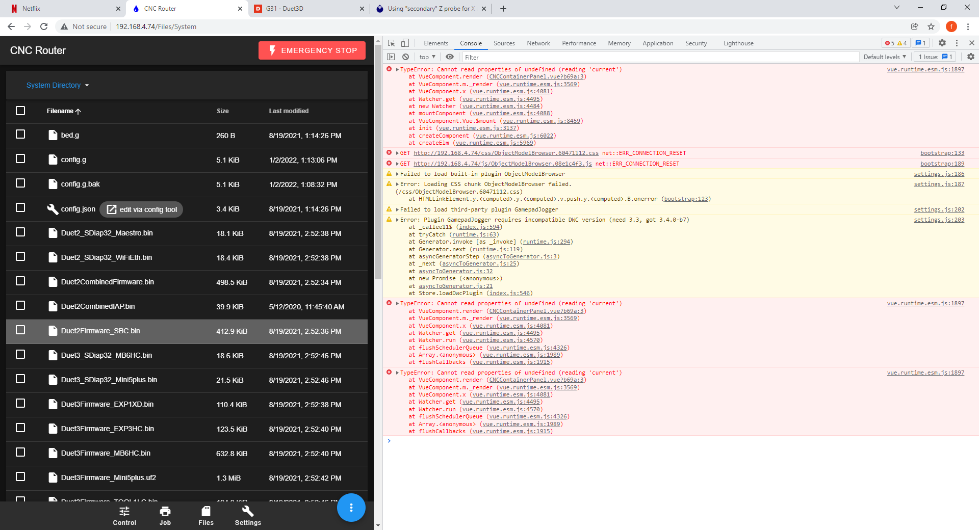
@baird1fa I am looking for browser errors which are causing the DRO portion to not display properly. For most browsers on PC hitting F12 brings up the browser’s console.
-
-
@baird1fa thanks that is what I was looking for. Looks like a value is coming in empty from the OM that needs to be accounted for. Thanks
In the mean time on general settings you can switch to the FFF dashboard and see the original screen until this gets resolved.
-
Any update on the fix for this issue. I keep checking for updates on the reprap GitHub but no new releases since November. Thanks.
-
@baird1fa this should be addressed when rc1 is released.
-
@sindarius Looks like it isn't fixed in the RC1 release. Is there a work around other than putting it in FFF mode? That seems to prevent some Gcodes from working like the spindle start for instance.

-
@baird1fa I cannot confirm this, it works as expected on my setup. Please check on the Settings -> General page that you are using 3.4-rc1 and press Ctrl+Shift+R if this is not the case to force-reload DWC.
-
@chrishamm My Bad I forgot to update the DWC and only updated the firmware. Thanks for the help.
-
 undefined dc42 has marked this topic as solved
