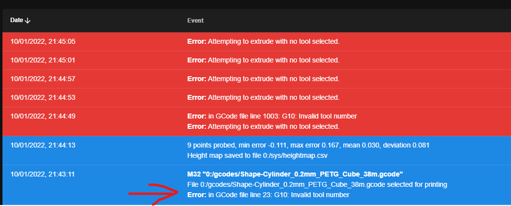
G10: Invalid tool number
-
I'm attempting to do a single extruder/hotend filament change (PETG to TPU) in superslicer but my Duet doesn't seem to like it.

At the filament change I get this error;

The printer stops extruding but the head keeps moving.
this is line 63804
G10 P1 S200 ; set temperatureIt looks like changing from P0 to P1 is the problem? but how do I get around this?
-
I found this example for a dual extruder in another post on this forum; see if it makes sense?
; Tools M563 P0 S"Head 1" D0 H1 F0 ; define tool 0 G10 P0 X0 Y0 Z0 ; set tool 0 axis offsets G10 P0 R0 S0 ; set initial tool 0 active and standby temperatures to 0C ; M563 P1 S"head 2" D1 H2 F0 ; define tool 1 G10 P1 X0 Y0 Z0 ; set tool 1 axis offsets G10 P1 R0 S0 ; set initial tool 1 active and standby temperatures to 0C -
@nick9one1 As @rjenkinsgb has indicated, you need to define the tools correctly in config.g. It might be best if you post that file so one of use can take a look. As well as that, there are a few other possible causes of your problem. The G10 command will set the active temperature but that in itself does not make the tool active - it merely sets the temperature that will will be used when the tool becomes active. There needs to be a Tn command in the gcode file to make "n" the active tool. So it would be good if you could post an extract from the gcode file for few lines either side of the G10.
Another possibility is inconsistent tool numbering compatibility between the slicer and the firmware. RepRap firmware (as used by Duet) expects the first tool number to be zero, the second 1 etc. Some slicers default to using the first tool number as 1, the second 2 etc. So it might be that you have tools 0 and 1 defined but the slicer is putting T1 and T2 commands in the gcode file. There is usually a setting somewhere in the slicer to configure the tool numbering system.
There are a few other possibilities but we'd need to see your configuration files and a sample of the gcode file you are trying to print, as well as any tool change macros if you use them.
-
Thank you both.
It does look like I only had one tool defined in config.g
I've added a second;
; Tools
M563 P0 D0 H1 F0   					 			 ; define tool 0
G10 P0 X0 Y0 Z0 								 ; set tool 0 axis offsets
G10 P0 R0 S0 									 ; set initial tool 0 active and standby temperatures to 0C
;
M563 P1 D1 H1 F0 						  		 ; define tool 1
G10 P1 X0 Y0 Z0 								 ; set tool 1 axis offsets
G10 P1 R0 S0 									 ; set initial tool 1 active and standby temperatures to 0C
The code @rjenkinsgb posted looks like it defines a different heater for tool 2? So I kept H1 on both tools ( presume this is the heater?)
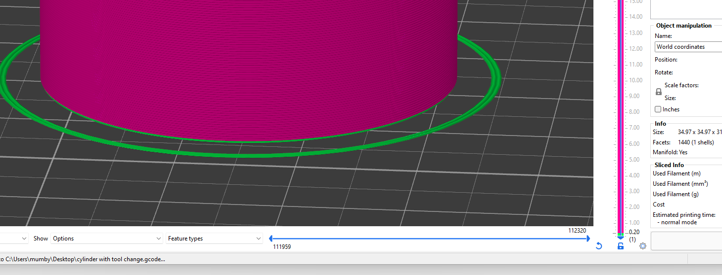
I've sliced a simple cylinder that changes at layer 1


and the gcode file:
cylinder with tool change.gcode
this is the offending line;
G10 P1 S200 ; set temperaturefull config;
; Configuration file for Duet 3 Mini 5+ (firmware version 3) ; executed by the firmware on start-up ; ; generated by RepRapFirmware Configuration Tool v3.2.3 on Thu Jul 01 2021 17:21:30 GMT+0100 (British Summer Time) ; General preferences G90 ; send absolute coordinates... M83 ; ...but relative extruder moves M550 P"BLV MGN Cube" ; set printer name M669 K1 ; select CoreXY mode M80 C"nil" ; ATX PS_ON on ; Network M552 S1 ; enable network M586 P0 S1 ; enable HTTP M586 P1 S1 ; enable FTP M586 P2 S0 ; disable Telnet G4 S1 ;wait for expansion boards to start ; Drives M569 P0.0 S0 D2 ; X motor runs forwards M569 P0.1 S1 D2 ; Y motor runs forwards M569 P0.2 S1 D2 ; physical drive 0.2 goes backwards M569 P0.3 S1 D2 ; physical drive 0.2 goes backwards M569 P0.4 S1 D2 ; physical drive 0.2 goes backwards M569 P121.0 S1 D2 ; physical drive 121.0 goes backwards M584 X0.0 Y0.1 Z0.2:0.3:0.4 E121.0 ; set drive mapping M671 X0:290:290 Y155:62:255 S3 ; leadscrews at rear left, front middle and rear right M350 X16 Y16 Z16 I1 ; configure microstepping with interpolation M350 E16 I0 ; configure microstepping with interpolation M92 X200.00 Y200.00 Z3200.00 E700 ; set steps per mm M566 X2000.00 Y2000.00 Z150.00 E150.00 ; set maximum instantaneous speed changes (mm/min) (Jerk) M203 X30000.00 Y30000.00 Z300.00 E2000.00 ; set maximum speeds (mm/min) M201 X9000.00 Y9000.00 Z200.00 E200.00 ; set accelerations (mm/s^2) M906 X1200 Y1200 Z900 E800 I30 ; set motor currents (mA) and motor idle factor in per cent M84 S30 ; Set idle timeout ; Pressure advance M572 D0 S0.07 ; Axis Limits M208 X-20 Y-20 Z0 S1 ; set axis minima M208 X305 Y295 Z200 S0 ; set axis maxima ; Endstops M574 X1 S1 P"121.io1.in" ; configure active-high endstop for low end on X via pin io0.in M574 Y2 S1 P"io6.in" ; configure active-high endstop for low end on Y via pin io1.in M564 H0 ; allow jog without homing ;M591 D0 P7 C"io5.in" ; filament sensor ; Z-Probe M950 S0 C"^121.io0.out" ; create servo pin 0 for BLTouch M558 P9 C"^121.io0.in" H3 F120 T10000 ; set Z probe type to bltouch and the dive height + speeds G31 P500 X0 Y66 Z2.45 ; set Z probe trigger value, offset and trigger height M557 X-10:293 Y65:300 P8 ; define mesh grid ; Heaters M308 S0 P"temp0" Y"thermistor" T100000 B3950 ; configure sensor 0 as thermistor on pin temp0 M950 H0 C"out0" T0 ; create bed heater output on out0 and map it to sensor 0 M307 H0 R0.291 C1127.4 D26.90 S1.00 ; Set PID for bed values M140 H0 ; map heated bed to heater 0 M143 H0 S100 ; set temperature limit for heater 0 to 100C M308 S1 P"121.temp0" Y"thermistor" T100000 B4725 C7.06e-8 ; configure sensor 1 as thermistor on pin 121.temp0 M950 H1 C"121.out0" T1 ; create nozzle heater output on 121.out0 and map it to sensor 1 M307 H1 B0 R3.089 C258.2:154.4 D5.95 S1.00 V23.7 ; Set PID for hotend values M143 H1 S280 ; set temperature limit for heater 1 to 280C ; Fans M950 F0 C"121.out2" Q80 ; create part cooling fan 0 on pin toolboard out1 and set its frequency M106 P0 S0 H-1 B1 ; set fan 0 value. Thermostatic control is turned off M950 F1 C"121.out1" Q100 ; create hotend fan 1 on pin toolboard out1 and set its frequency M106 P1 S0.8 H1 T45 ; set fan 1 value. Thermostatic control is turned on ; Tools M563 P0 D0 H1 F0 ; define tool 0 G10 P0 X0 Y0 Z0 ; set tool 0 axis offsets G10 P0 R0 S0 ; set initial tool 0 active and standby temperatures to 0C ; M563 P1 D1 H1 F0 ; define tool 1 G10 P1 X0 Y0 Z0 ; set tool 1 axis offsets G10 P1 R0 S0 ; set initial tool 1 active and standby temperatures to 0C ; Accel M955 P0 C"io3.out+io3.in" ; Screen M575 P1 B57600 S1 -
@nick9one1
Looking at the output, I see a couple of issues and potential issues.- Your M98 call to the filament purge macro incorrect. It should probably be M98 P"0:/macros/Filament/Purge"
- The first call to T0 occurs AFTER the call to purge, so unless you have T0 or another tool selected before the print starts, it will fail when it tries to purge.
- Your code to retract filament is BEFORE you have selected T0, so again will fail if a tool wasn't selected before the print starts.
M109 S235 ; wait for extruder temp M98 P"0:/macros/Filament/Clean Nozzle" ; Clean nozzle macro M98 P/macros/Filament/Purge ; Run nozzle purge macro G1 E-0.1 F2000 ; Retract 0.1mm filament G92 E0 ; reset extruder ; custom gcode end: start_gcode G21 ; set units to millimeters G90 ; use absolute coordinates M82 ; use absolute distances for extrusion G92 E0 T0 G92 E0 -
Thank you, I'll fix that and try again.
Although the print does start and prints fine until the tool change (line 1006).
Single filament prints work fine too. -
I've removed the macros as I dont use them (the files dont exist so always skipped anyway).
; custom gcode: start_gcode T0 ; Select Tool 0 M104 S235 ; set extruder temp ;--- Display M73 remaining time M140 R-0 G10 P0 R-38 ;--- M140 S55 ; set bed temp ;--- Display M73 remaining time M140 R-0 G10 P0 R-38 ;--- G21 ; metric values M190 S55 ; wait for bed temp G28 ; home all ; Replaced marker: M557 TBD ; parameters will be set automatically M557 X182:245 Y41:104 P3:3 ; End marker G29 ; Mesh bed probe G29 S1 ; Load compensation map G92 E0 F100 ; reset extruder G1 Z10 F3000 ; move z up little to prevent scratching of surface M109 S235 ; wait for extruder temp G1 E-0.1 F2000 ; Retract 0.1mm filament G92 E0 ; reset extruder ; custom gcode end: start_gcode G21 ; set units to millimeters G90 ; use absolute coordinates M82 ; use absolute distances for extrusion G92 E0 -
There is actually an error in the console earlier than I thought, I missed it as its not in red.

G10 P1 R200 ; sets the standby temperature -
Can you send M98 P"config.g" and see what errors you get?
Can you share the gcode file in question? -
I think I've found the problem. The second tool I added to config.g had D1 instead of D0.
The printer only has one hotend and extruder so they are 'virtual' tools that let me change filament print settings (temp, retraction etc.) in the slicer.; Tools M563 P0 D0 H1 F0 ; define tool 0 G10 P0 X0 Y0 Z0 ; set tool 0 axis offsets G10 P0 R0 S0 ; set initial tool 0 active and standby temperatures to 0C ; M563 P1 D1 H1 F0 ; define tool 1 G10 P1 X0 Y0 Z0 ; set tool 1 axis offsets G10 P1 R0 S0 ; set initial tool 1 active and standby temperatures to 0C