Broken Stepper Driver and/or MOSFET
-
Hey guys,
so while building my new printer I made a pretty stupid thing... V_In and GND of my 3HC Expansion were mixed up. As expexted the fuse was blown and I heard some crackling.
Short Version:
I will need to replace the Stepper Drivers and/or MOSFETs. Does anyone know the exact type of these components?
Because in the schematic there is only TMC5160. But there are multiple variants of this device even in the TQFP package.
Also the MOSFETs are not specified.Long Version:
I was adding the configuration for the drivers of the expansion board. These will be extruder drives. I already had everything setup for the mainboard. The drives on the mainboard are XYZ. So I just copy and pasted everything accordingly. Therefore I don't expect any problems in the configuration or G-Codes.
When trying to run the extruder motors all of them would just make a very quiet snizzling noise like I would expect it, but they wouldn't move. I know the motors are connected correctly and working as expected because I tested them on an empty driver port of my mainboard and also an older different mainboard I have.
So, I know the motors and cables are good, the software and configuration is good, so only hardware is left.
Checking the schematic of the expansion board I think the only thing that is in danger of getting a reverse polarity supply voltage are the drivers and corresponding MOSFETS. And maybe the MOSFETS for Out0,1,2, although the are "protected" by D11,13,15.Any other ideas or suggestions?
Thanks! -
@mws the drivers can be TMC5160, TMC2160, or the A versions of either of those - it doesn't matter because as far as RRF is concerned, they are all compatible.
If your EXP3HC board is version 1.0a or earlier (not 1.01) then the mosfets are DMT6018LDR. You may find these hard to obtain due to the current electronic component shortage.
It's hard to know whether the drivers have protected the mosfets, or the other way round, or neither. Do either the mosfets or the drivers show damage? You could meter the mosfets to check whether they are shorted. If they are, then you could remove them and then power up using a low-current PSU to see if the drivers are OK.
Duet WiFi hardware designer and firmware engineer
Please do not ask me for Duet support via PM or email, use the forum
http://www.escher3d.com, https://miscsolutions.wordpress.com -
@dc42 Hi, thanks for Your response. I will try to get the components and report my results. Maybe someone else will find it helpful in the future.
Neither the MOSFETs nor the drivers show damage, not even under a microscope. I don't believe the MOSFETs are shorted, because I was able to power up and use all other functions of the 3HC by simply replacing the fuse. Also I was able to hear the typical "power electronics is switching"-noise, although it was not as loud as in normal operation. This noise also nearly stopped when the motor current was decreased to idle current.
Would you recommend replacing both MOSFETs and drivers right away or maybe try replacing only one of these and hope it works?
I guess I would just change all MOSFETs and drivers right away. Since this procedure will take a lot of time anyway, so what's one switch more or less... -
@mws what does M122 show for the status of the three drivers? If it looks sensible then the SPI interface is working, so the drivers are at least partly OK. OTOH if it doesn't look OK then the drivers have failed.
You could meter between the stepper output pins and VCC, and between the outputs and ground, using the meter on the diode test function to see if the mosfet body diodes still read correctly.
Duet WiFi hardware designer and firmware engineer
Please do not ask me for Duet support via PM or email, use the forum
http://www.escher3d.com, https://miscsolutions.wordpress.com -
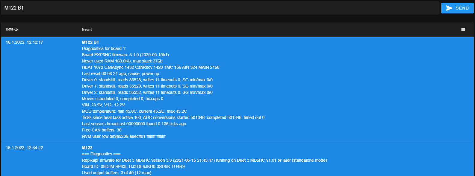
@dc42 Thanks for your recommendations. I have run the M122 for the expansion board in question. See the screenshot attached. By comparing with the diagnostics from the main board, I believe this is looking ok.
I also metered all the body diodes. In reverse they are all blocking. In forward they all have about 540 mV, which I think is a reasonable value.
Since these results can't really explain whats wrong I did one more thing:
- Taking a stepper that I know is working and reassuring this by quickly testing it on a stepper port that I know is working. It works.
- Connecting this stepper to one of the presumably broken stepper ports on the expansion board
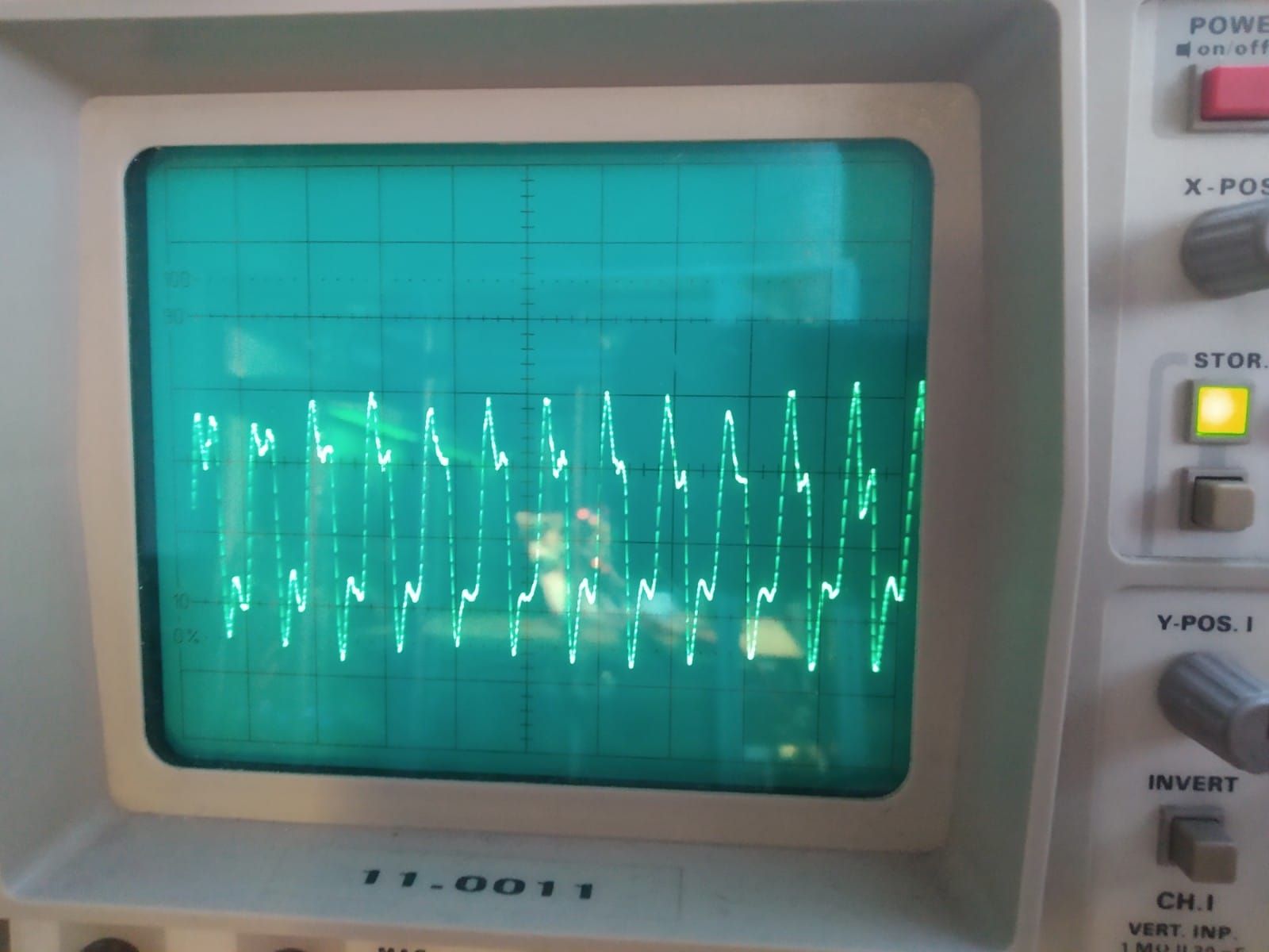
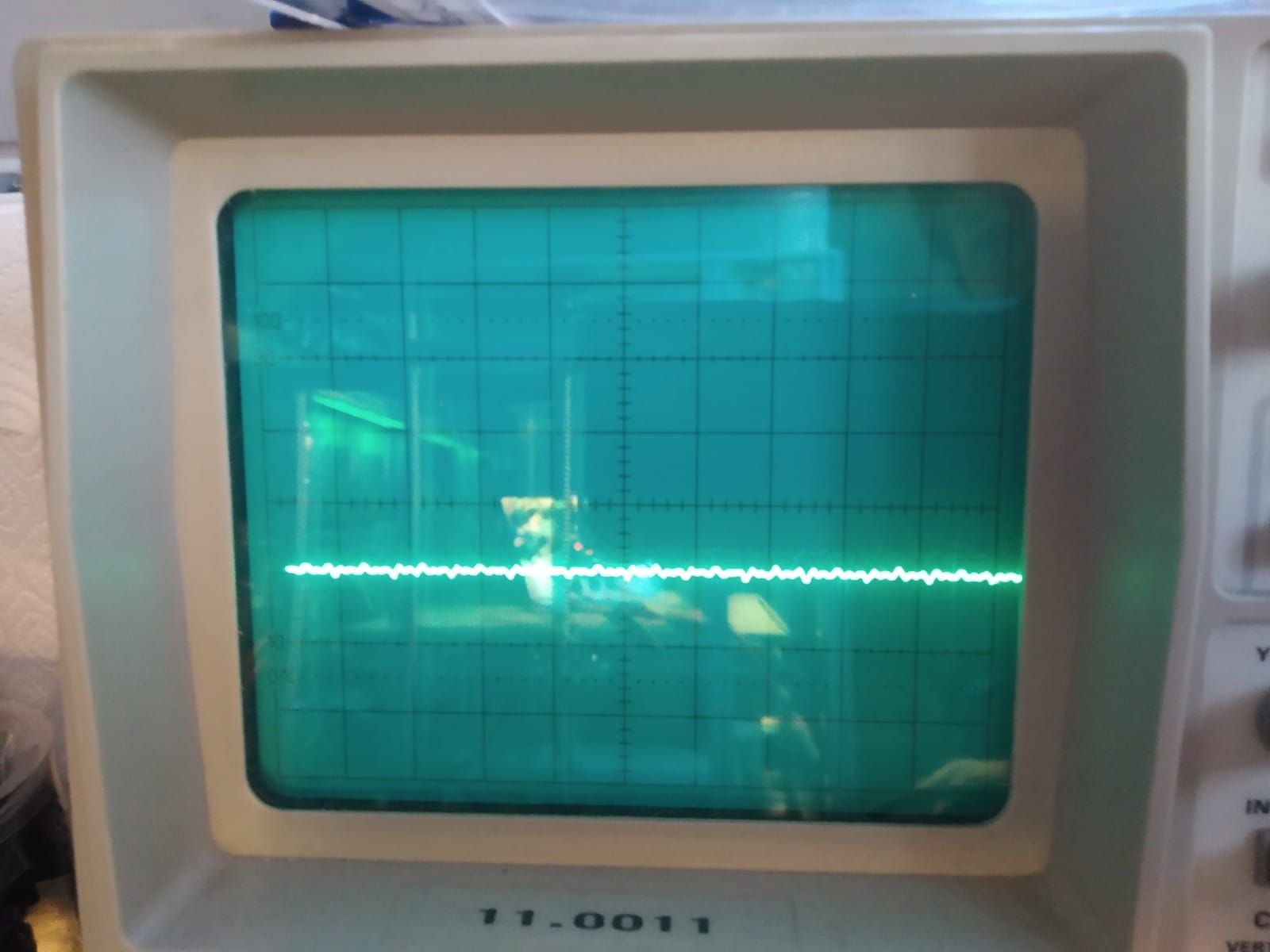
- Connecting an oszilloscope first between DRIVER_0_A1 and DRIVER_0_A2 and second between DRIVER_0_B1 and DRIVER_0_B2. Unfortunately I don't have differential probes at home, so I had to take two separate measurements. See pictures attached.
The pictures are 10V/div and 20ms/div.
I assume the first one looks as expected, since there is some more or less clean switching between +Vcc and -Vcc. I use 24V. I believe the small oscillations are to be expected and partially due to my low quality measurement gear.
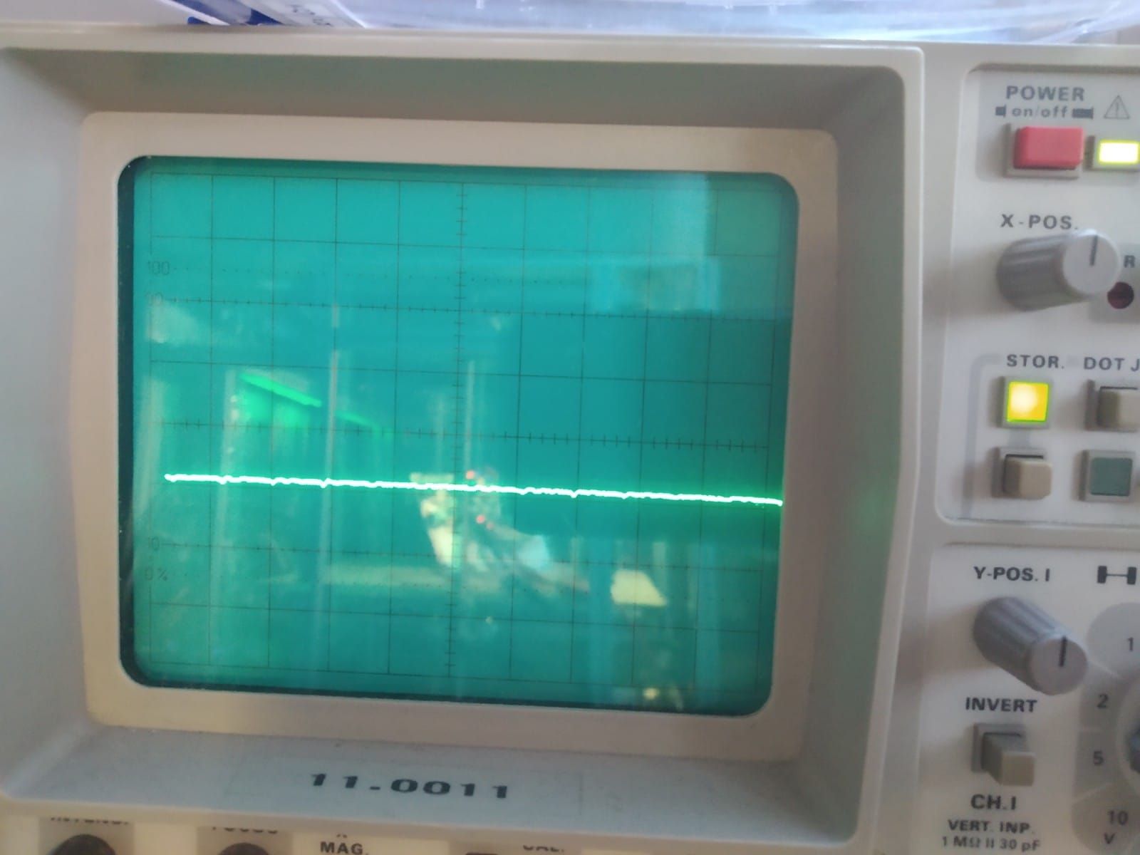
But on the second picture You can see that there is nothing happening on phase B.
This also explains why I can hear the motor switching very lightly but nothing moves.
The other two stepper ports of the expansion board show the same results.
So it appears that phase B is broken. I couldn't tell why, since on the schematic I see absolute no difference between the two phases.


Finally, I also connected the oszilloscope directly to the stepper drivers and measured between HB1-DRIVER_0_B1, HB2-DRIVER_0_B2 and LB1-GND, LB2-GND, so the gate signals to the MOSFETs. See pictures attached. This time it is 50mV/div. For HB1 and LB2 some 100mV is definetly to little to make a MOSFET switch. also the waveform looks uncommon. For HB2 and LB1 there is nearly nothing happening. This time I only measured Driver 0, since I had to solder tiny wires to the pins which is very annoying. I will assume the other two drivers will behave the same.
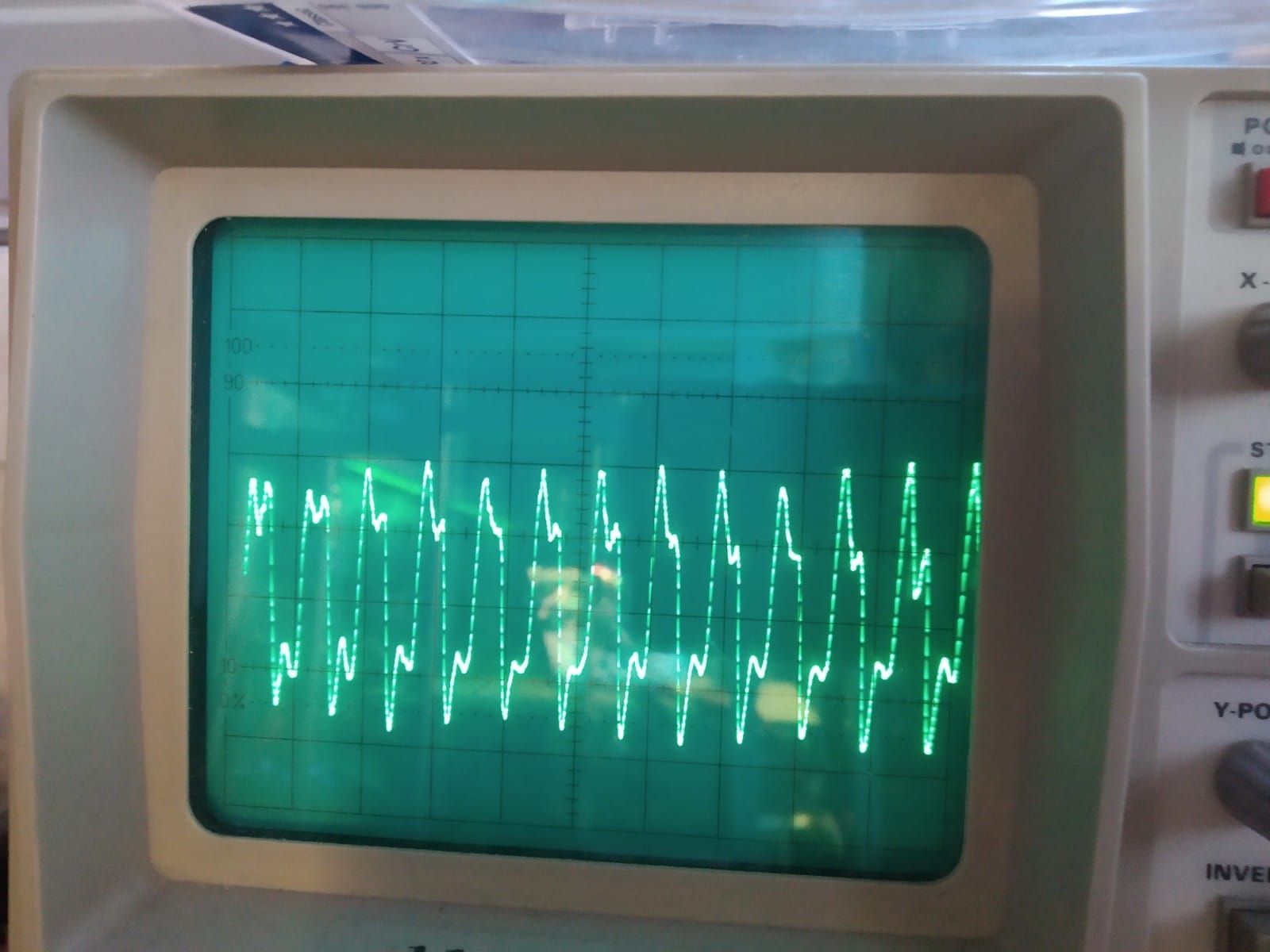
So in conclusion I definetly think I broke the stepper drivers. I can't tell if the MOSFETs are broken too. The body diode seems to be fine. I think this would have been the only thing to break the MOSFETs in a reverse voltage event.
I will try to get my hands on some replacement parts and post my experiences.
Thanks again for Your help.