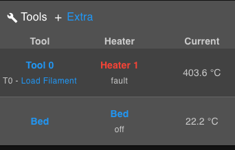
[3.4.0beta6] After update: Heater 1 fault shows 409.9 °C
-
Thank you @dc42
I did it but the problem persist, this is the temp 0 with the beta 5:

09/11/2021, 12:42:35 m122 b20 Diagnostics for board 20: Duet TOOL1LC rev 1.1 or later firmware version 3.4.0beta5 (2021-10-12 13:59:06) Bootloader ID: SAMC21 bootloader version 2.3 (2021-01-26b1) Never used RAM 3032, free system stack 2789 words Tasks: Move(notifyWait,0.0%,153) HEAT(notifyWait,0.1%,115) CanAsync(notifyWait,0.0%,64) CanRecv(notifyWait,0.0%,77) CanClock(notifyWait,0.0%,64) ACCEL(notifyWait,0.0%,61) TMC(notifyWait,2.9%,67) MAIN(running,92.1%,440) IDLE(ready,0.0%,27) AIN(delaying,4.9%,148), total 100.0% Last reset 00:00:03 ago, cause: software Last software reset time unknown, reason: AssertionFailed, available RAM 3392, slot 2 Software reset code 0x0120 ICSR 0x00000000 SP 0x2000415c Task Freestk 129 bad marker Stack: 00000544 00022ffc 00019b65 20003134 00016cff 20003134 000163d1 20000ed0 00000000 00000001 00008275 200071c8 200071c8 200071e0 00000000 20000f50 00011647 000223b8 00022474 00021ac8 00019b05 200071c8 200071c8 20000f50 000083ed 200071d8 000009c7 Driver 0: pos 0, 80.0 steps/mm, standstill, SG min/max 0/0, read errors 0, write errors 1, ifcnt 49, reads 1870, writes 9, timeouts 0, DMA errors 0, steps req 0 done 0 Moves scheduled 0, completed 0, in progress 0, hiccups 0, step errors 0, maxPrep 0, maxOverdue 0, maxInc 0, mcErrs 0, gcmErrs 0 Peak sync jitter -2/5, peak Rx sync delay 564, resyncs 0/0, no step interrupt scheduled VIN voltage: min 24.0, current 24.0, max 24.0 MCU temperature: min 35.4C, current 35.4C, max 35.4C Last sensors broadcast 0x00000000 found 0 42 ticks ago, loop time 0 CAN messages queued 59, send timeouts 0, received 45, lost 0, free buffers 37, min 37, error reg 0 dup 0, oos 0/0/0/0, bm 0, wbm 0, rxMotionDelay 0 Accelerometer detected: yes, status: 00 I2C bus errors 0, naks 3, other errors 0 -
@juliann it sounds like a hardware fault then, assuming you are using exactly the same M308 parameters for temp0 as for temp1. But you should also check that the protruding pins on the back of the tool board are not touching anything conductive, and there is no metal swarf on the board.
You could also try running the calibration procedure on temp0 as described at https://duet3d.dozuki.com/Wiki/Calibrating_thermistor_and_PT1000_readings, although I doubt that bad calibration parameters would give such a large error.
-
@dc42 said in [3.4.0beta6] After update: Heater 1 fault shows 409.9 °C:
https://duet3d.dozuki.com/Wiki/Calibrating_thermistor_and_PT1000_readings
Yes, I am using exactly the same M308 parameters.
When I try to run the semi-automatic calibration procedure (I already tried with both beta firmwares) I get this message (with all temp sensors unplugged):
M308 S1 H999
Error: M308: Computed correction is not valid. Check that you have disconnected the thermistor.Anyway the temp 0 always shows between 200 and 410 °C which it depend if the thermistor is plugged or unplugged.
Thanks!
Julián. -
Sorry I forgot to mention, there is no possible contact in the back of the toolboard everything is plastic and it is correctly protected to avoid issues.
-
@juliann please email warranty@duet3d.com. You will receive a response with a link to a form to fill in.
-
-
 undefined juliann has marked this topic as solved
-
 undefined juliann has marked this topic as unsolved
-
Hi @dc42
Sorry, the problem persists.
I received the Toolboard replacement and worked perfect during the first 5 prints.
During the last one, a heater 0 fault suddenly appeared interrupting the printing (while reading 241°).
After pressing emergency stop, the temperature reading went to 980° (just the reading, not actual temp).
The ambient reading now is 280° no matter if I reset of turn off/on the printer.So I did the same as before, I changed the temp port in the toolboard and now in the temp1 it seems to work again. Any ideas?
Thanks again
Julián. -
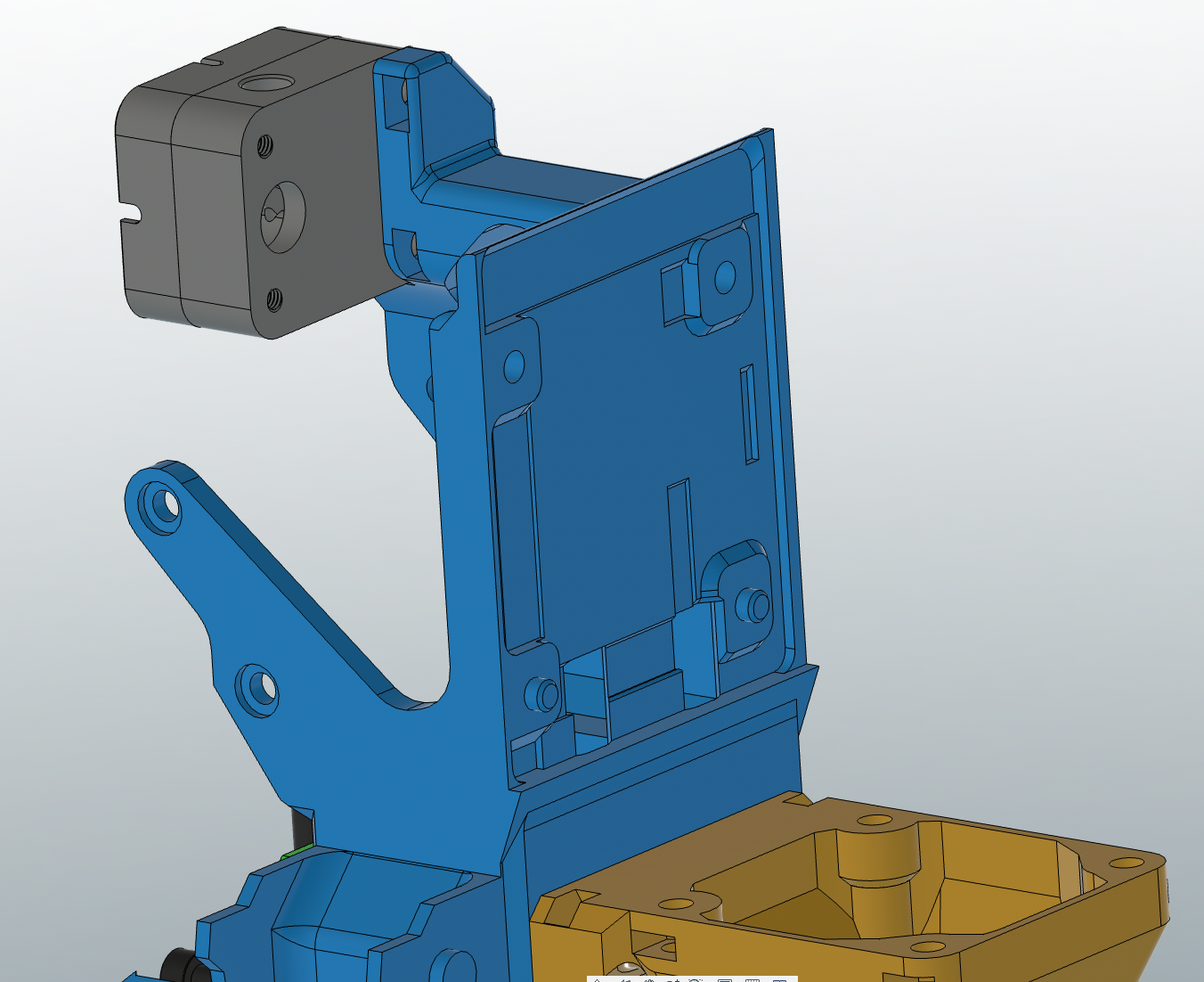
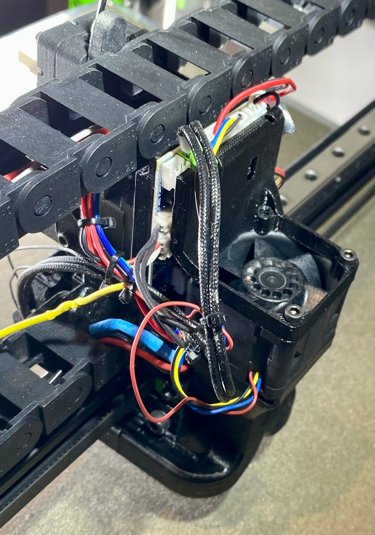
@juliann Please can you send a picture of how the board is mounted and wired. A good clear high resolution picture of the board itself as well.
In addition please check carefully for any shorts between your thermistor and the hotend heater wires.
-
Thank you @t3p3tony
All the parts in contact with the tool board are plastic, just two screws are used to mount it. At this moment I am using the temp1 of the tool board without issues (same way as I did before with the previous one).
If I switch back to temp0 the problem persists.As I just replaced the tool board the current wiring is not organised, I just put a coupe of ties to keep cables in a safe position.
Please let me know if you need more photos/ information.


-
@juliann I have received and examined your first tool board that showed this problem. The fault is caused by a burned-out reference resistor. The only reason I can see that resistor would burn out is if the TEMP0 input is shorted to a 24V supply for more than a few seconds.
As this has happened to two tool boards, what I think is happening is that you have an intermittent short circuit between the thermistor and the hot end heater. There are various ways this might occur, including these:
- A hot end heater and thermistor wires touching where they are not insulated
- Hot end heater cartridge shorting internally between the element and the case when it gets hot, and the thermistor wire touching the hot end metalwork
Unlike most 3D printer control boards, Duets are normally resilient to this type of short circuit - and the tool board microcontroller was indeed protected in this instance. However, the small size of the resistors used on the tool board means that the sense resistor cannot tolerate a short circuit to 24V for more than a few seconds before it fuses.
I have replaced the resistor and the board is now giving the correct temperature readings, I will contact you to arrange a swap of this a tool board with the one you currently have. Meanwhile, please locate and fix the intermittent short circuit.
-
Hi @dc42
I just got you email, thank you very much for the detailed explanation.
I will recheck very carefully all the tool board wiring and send it back to you.Thanks again
Julián. -
 undefined pasque referenced this topic
-
 undefined pasque referenced this topic
-
@juliann you should have received your repaired tool board by now.
I have received and examined your second tool board. It has the same problem, i.e. the series resistor has gone open circuit.
I originally thought that only a short from TEMP0 to +24V cold cause this type of failure, however on researching this I have read that small resistors can be damaged by ESD. So if you are sure that there have been no shorts, then it is likely that ESD caused the failures.
The best way to guard against ESD would be to connect the hot end metalwork to ground on the tool board, either directly or through a resistor in the range 10K to 1M. You can pick up a ground connection on the IO_ connectors. The advantage of using a resistor is that if you get a short between the hot end metalwork and the heater cartridge, the tool board will be protected from damage.
-
Hi David @dc42
I am currently rewiring the the ground using a 10K resistor.
Before you send me this message I bought another Toolboard v1.1 and installed it with a new thermistor and heater, but after a few prints I got the same issue (with temp0) so I think you are right, as there is no chance to have been shorts in the installation an ESD should be the explanation.BTW I already received this morning the repaired tool board.
After finishing this installation, can I send you this second tool board to repair it as well?
Thank you!
Julián. -
@juliann said in [3.4.0beta6] After update: Heater 1 fault shows 409.9 °C:
After finishing this installation, can I send you this second tool board to repair it as well?
Yes, please do.
-
 undefined juliann has marked this topic as solved