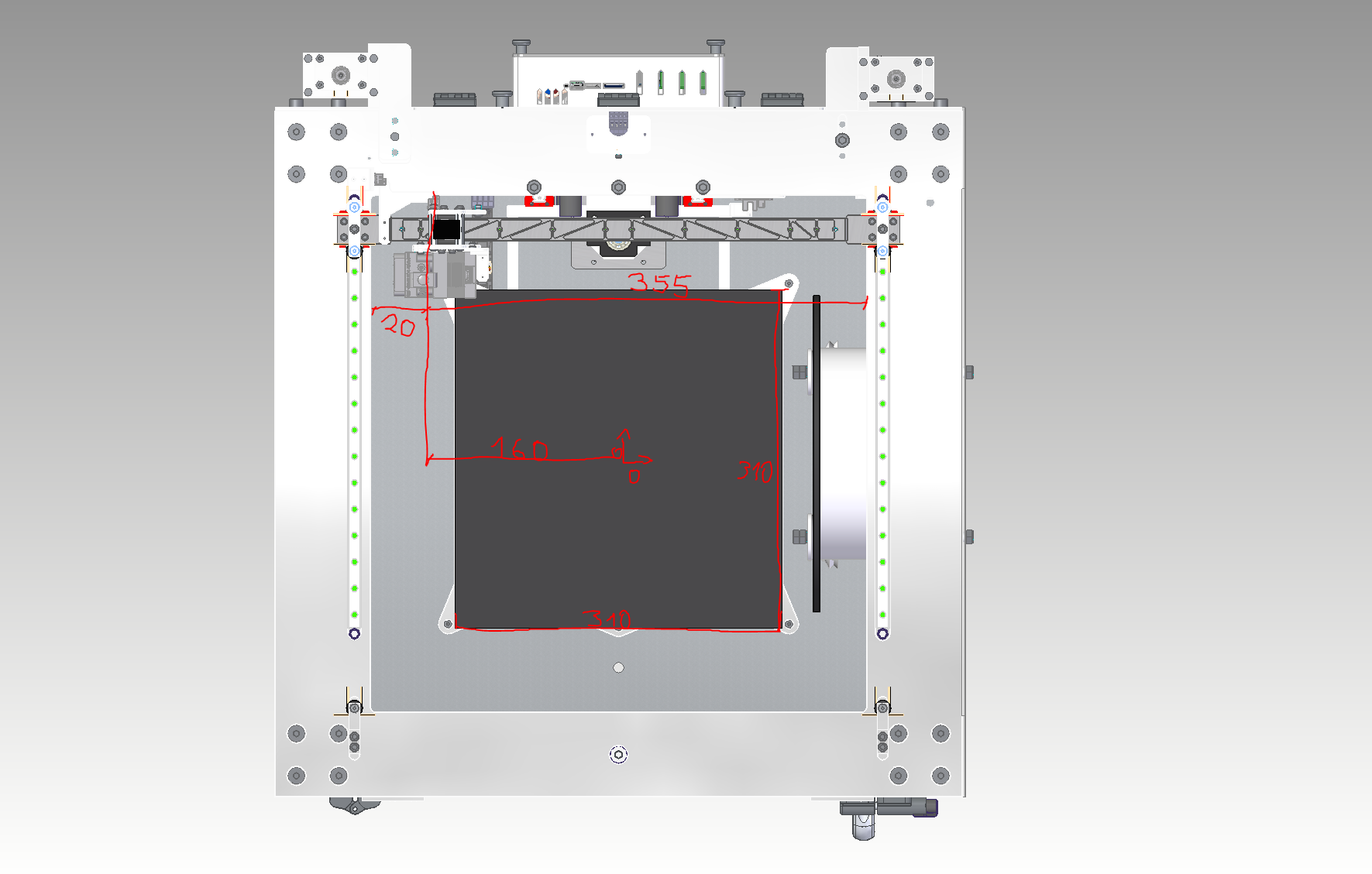
Bed Origin and axis Limit
-
@n3xt3d The X axis endstop doesn't need to be on the extruder carriage. It can be mounted on the printer frame, reducing the number of moving wires that have to attach to the carriage. When you configure it, you set it up to always home Y first, then X. I've had my printer set up this way for a couple years, and never missed the ability to home X independent of Y.
Endstop locations define the home position, which is not necessarily the same as the origin. When you tell the machine to home, the carriage should move toward the endstops. You define where the origin of the machine is when you assign the values to the endstops. if you assign a value of 0 to both, you set the origin to the same location as the endstops, but you don't have to do that.
Slicers always try to arrange prints around the center of the bed. If you use multiple slicers, it is easiest to set them up for your printer if you set the printer's origin to the center of the bed. I wrote a blog post on setting it up this way here.. Let's say your bed is 400 x 400 mm. If the endstops are located at the edges of the bed, you can set the machine's origin to the center of the bed by assigning values of +/-200 at the endstops (+/- depending on which specific edges of the bed the endstops are located).
-
@mrehorstdmd Thanks for the tips.
Putting the origin point in the center of the bed should solve the problem.
I will leave the endstop layout as it is for the time being, as I already have some lasered aluminum parts here. But basically a good idea.
By the way, I have read some of the articles on the layout of Corexy printers and I would like to thank you for them.
This is the most helpful information you can get.So thank you

-
@mrehorstdmd But even with this variant there is the problem that you can never drive past the trigger point of the end stop. Or am I wrong?
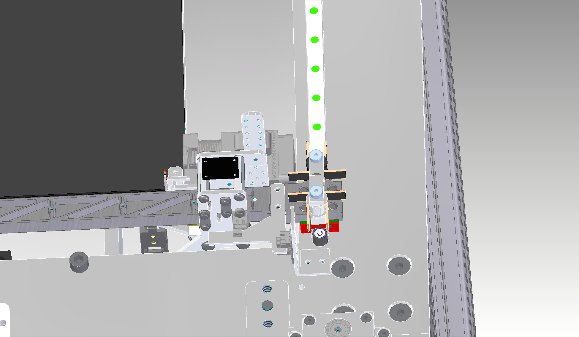
For example, these two views would be the point at which the optical end stop triggers. You couldn't go any further into the negative and I wouldn't be able to use 20mm of the rail


As an example for the X axis, the limit of the axis and the origin of the bed would have to be set separately (in relation to the trigger point of the respective axis).

Otherwise it would not be possible to use the entire length of the rail, as shown in the next picture

I hope the screenshots from the different perspectives and what I want to explain are understandable.
-
@n3xt3d The origin and the home position are two different things. You can place them at the same location, but it isn't necessary to do so. The home position is defined by the endstops. It can be at any corner of the addressable XY space. The origin can be at any location within that XY space, not just at the corners. Slicers want to know where the origin of the machine is and don't care about the endstops. That's why it is very convenient to put the origin at the center of the bed plate.
I don't understand why your X axis flag has to be so long. Are you trying to get the home position to line up with the corner of the bed? You can assign a negative value to a home position, so for example, if you set the X home position to be 20 mm from the edge of the bed and you want the origin at the edge, set the minimum value for X to be -20. You don't have to use a single flag to trigger both endstops. Maybe you just have to get a little more creative with the endstop and flag positioning.
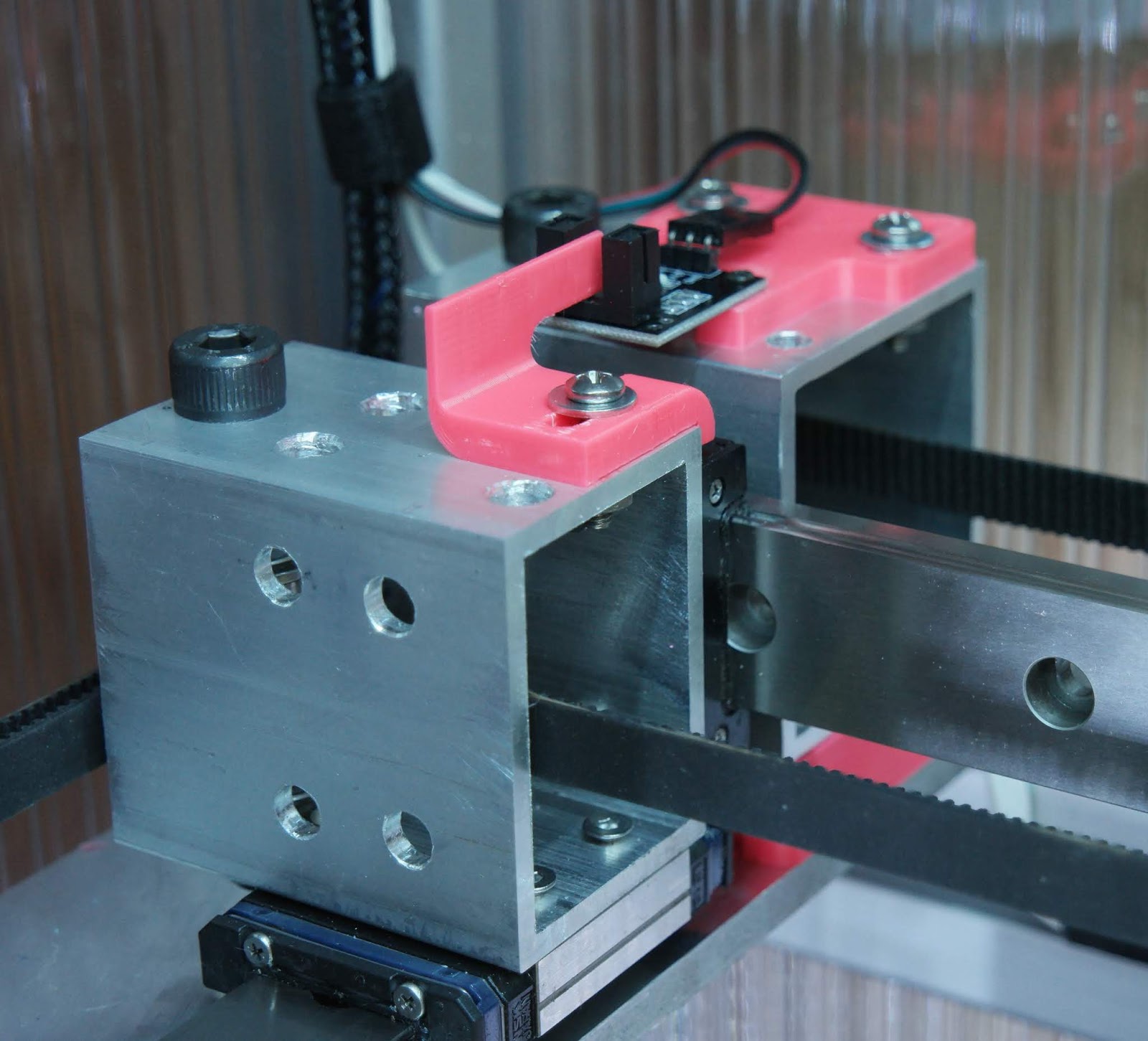
Here's my Y axis endstop, with the stop mounted on one of the corner pulley blocks and the flag mounted on the Y axis bearing block (left rear corner of the XY space):

The Y axis can home regardless of the extruder carriage position.
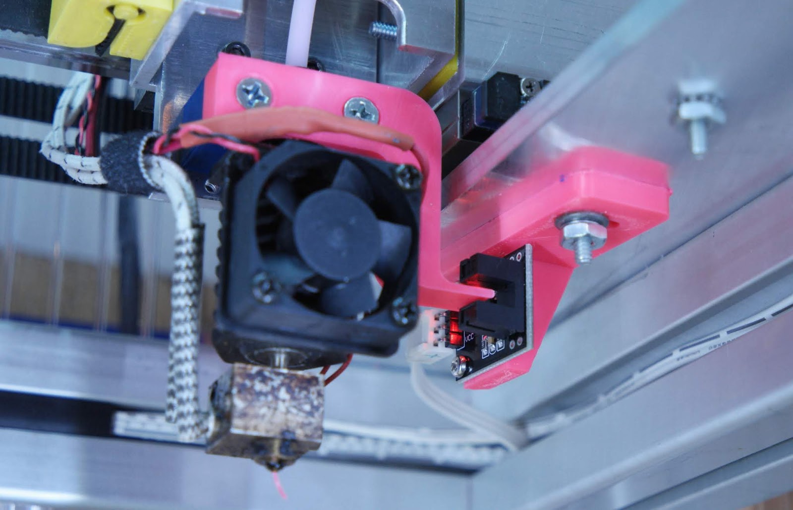
And here's the X axis endstop, at the opposite end of the X axis (right rear corner of the XY space), with the flag integral to the hot-end clamp on the extruder carriage:

With my endstop/flag arrangement, the X axis can only be homed if the Y axis is in the home position, so the homeX.g file homes Y first, then X. That way, if I ever forget that Y needs to be homed first, and try to tell it to home X, it will work without crashing. HomeAll calls the homeY.g, homeX.g and homeZ.g files, so that works fine, too.
I had the printer at the makerspace for a while and let others operate it, and no one managed to crash it. Incidentally, if you ever want to know if your 3D printer design/build is operator-proof, take it to a makerspace and let some cosplay people print with it. If there are any flaws in the design or construction, they will find them very quickly.
-
@mrehorstdmd said in Bed Origin and axis Limit:
I don't understand why your X axis flag has to be so long.
I cannot tell from his images exactly what his printer is doing.
But on one of mine, using beam-break optical endstops, the endstop mounting positions are such that the flag initially triggers them around 20-30 but motion can continue to 0.
The flags are long so that even when at 0 the endstop sensor is still triggered.
Frederick
-
@fcwilt The OP is worried about losing 20mm of motion, but based on the last picture he posted, all he has to do is cut the X flag 20mm shorter. I'm not sure why you'd want or need to use long flags. Once an axis has been homed, its endstop is ignored, so it doesn't matter if the flag is still in the endstop or not. Why would you want to trigger the endstop 20-30 mm before the end of the axis?
-
First of all, thank you for all the help.
ok maybe there were too many different views. Sorry
At first I thought I would leave the flag longer and I can shorten it later, but then I thought why not leave it longer and relate the minimun of the axis to the trigger point. Too short wouldn't be good either.
My idea is to leave the flag a little longer (not necessarily as much as in the illustration. Let's say 5mm) and to use the "softlimit" to limit the axis so that it does not reach the mechanical end stop.
Maybe I'm just confused, but is it possible to say that the limit of an axis is 5mm behind the trigger?
-
@n3xt3d I'm not sure if you can do that in the X and Y axes. I believe it is possible in the Z axis- you can trigger well away from the point at which the nozzle would crash into the bed and then apply an offset to get it to zero. I'm still not sure why you'd want to do that. If you put the endstop a mm or two from the mechanical stop you're getting almost all the motion the machine is capable of. Don't worry, the mechanism can still bang into the mechanical stops if the controller malfunctions. There's only so much you can do...
I make the flag and/or endstop switch positions slightly adjustable to allow for my miscalculations or measurement errors.
-
@mrehorstdmd Yes 1-2 mm are definitely not a problem. For me, it's all about being able to reach a brush that is outside of the printable area, for example. That's all

I think I'll then shorten the flag as much as necessary so as not to complicate things.
Thank you for the hard work and the detailed answers.
Have a nice weekend.
-
@n3xt3d you can fudge your homing to work like you mentioned by using the same principle as for z-endstop homing.
In your homing file, do a normal homing move to the endstop. This sets that position to be the axis minima (say to -165mm). Then use G92 X-160 to tell the machine it's actually at x=-160mm. Hey presto, tha machine can now travel past your endstops

Just make sure that yout back-off move is greater that the exta offset you use
-
@engikeneer this is really a clever solution. Exately what I was looking for! Thanks

-
@mrehorstdmd said in Bed Origin and axis Limit:
@fcwilt The OP is worried about losing 20mm of motion, but based on the last picture he posted, all he has to do is cut the X flag 20mm shorter. I'm not sure why you'd want or need to use long flags. Once an axis has been homed, its endstop is ignored, so it doesn't matter if the flag is still in the endstop or not. Why would you want to trigger the endstop 20-30 mm before the end of the axis?
I didn't want it to trigger there but that was where I could mount the endstop sensor.
And it does matter if the flag remains in the sensor on my printer.
If the flag was able to clear the sensor when near or at 0 then homing would not work correctly since the 1st move would be to move toward 0 but it would already be past the sensor and thus the sensor could never be triggered on the 1st move.
With the flag remaining in the sensor from the first trigger position (20-30) all the way to 0 the first move either moves toward the sensor OR does not occur since the sensor is already trigger.
In either case the 2nd and 3rd moves occur normally.