New to Duet but heading to a major project. Advise needed.
-
If your contact is telling you COM1+ on CN5 is the power supply for the motor, you still need to get in touch with someone more knowledgeable at their company.
COM1+ Is not the power for the motors.
Motor power is supplied via M24V on connector CN1 according to the document you linked to in your first posting.If these folks built a 24-Volt only controller you don't want to work with them anyway.
-
@alankilian said in New to Duet but heading to a major project. Advise needed.:
If your contact is telling you COM1+ on CN5 is the power supply for the motor, you still need to get in touch with someone more knowledgeable at their company.
COM1+ Is not the power for the motors.
Motor power is supplied via M24V on connector CN1 according to the document you linked to in your first posting.If these folks built a 24-Volt only controller you don't want to work with them anyway.
Ok, I understand what you mean, but it seems to me that there's a confusion somewhere.
Obviously the motor and driver main supply are in CN1. It may not explain me well, my fault.
However, in CN5, which is the connector that has to be wired to the Duet 1XD, pin 1-COM + is powered at + 24v, and internally also powers the I/O pins of the driver, except ±NP and ±PP.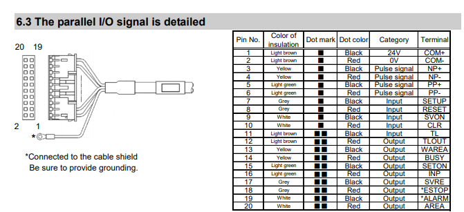
It is not like this? How would you connect it according to your suggestion to the Duet board? Do you still think it is possible?
I do not rule out that the SMC technician could have no idea, what it may be, or that I am not interpreting the data correctly.
-
I found this other schematic that draws two power supplies. It is true that I don't understand what the source connected to COM+ uses for.
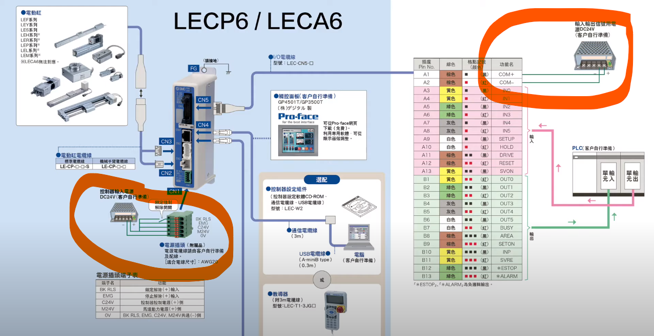
I'll ask for clarification asap.
-
You'll have independent z-axes? I was building a machine like this in the past. Here is a relevant thread for dealing with the different z-axes offsets. It worked well enough.
https://forum.duet3d.com/topic/18051/printer-with-two-independent-z-axes-how-to-synchronize
-
If you want to use this device and follow the instructions of your technician, you can build a pretty simple board that converts all the signals you need.
Or you can buy some existing boards to convert the levels for you.
I would recommend just buying the level translator boards you need and wire them up.
-
If possible i would avoid having two sets of optocouplers in the system (from Duet 3.3V/5V signals ->24V and then from 24V on the input to the servo logic) each optocoupler increases the delay which reduces your maximum step rate. and increases direction hold time.
look for fast level shifting options, either off the shelf of you can make a custom board.
-
Okay, signal conversion would work, but still there aren't enough I/O pins on the 1XD board to control all the signals received from the servo.
I'd better get other solutions like Oriental Motors or Clearpath with closed loop servos but only using DIR / STEP signals. SMC drivers seem too advanced for this controller. We won't to unnecessarily complicate the machine just by wanting use certain HW.
-
I think we've found a feasible alternative to SMC drivers.
It's from OrientalMotors, and it is their AZD-K controller:
http://www.orientalmotor.eu/msites/az/en/
It has internal closed loop with absolute encoder BUT can be controlled just with 4 signals, STEP and DIR at 5V_10mA, and apparently without using additional control pin. The closed loop position correction it's done internally in the driver controller.
I'll ask them for a demo unit, to see if can work with Duet 1XD board.
I have the doubt of how to homing the axes with this configuration. It is assumed that a G28 XO Y0 Zxxx could also be sent and as it already know where its absolute origin is, it would be positioned at zeroes before being able to move to print, although the Duet does not have real position feedback.
What do you think about? It' would work?
-
if its not a secret , can you tell what are you trying to extrude that needs those overkill actuators and servos , for such a small printing volume (200x200x100) ?
-
Microdosing of drugs and biochemicals. And other things like inkjet heads, spectrographs in the future ...
-
@Marcossf any reason not to use homing on the Duet using standard endstops? move an axis to a limit whith and endstop trigger - that position is then known by the Duet (at whatever the limit is set in firmware) then proceed from there. The "absolute" psotion read internally by the servo and used for closed loop control does not need to match the position the Duet is using.
-
@T3P3Tony Wiring and possible points of failure.
The printer internal environment and moving parts must be as clear, free of cables and protrusions as possible for the user.The previous functional proto we made used sensorless with the TMC drivers, which works reasonably well, and putting endstops is a step backwards.
The home position with an absolute encoder like this would ensure that the mechanical zero position is always exactly the same. Simply the Duet controller would have to know that this position is the zero point, before starting any movement.
I do think it is possible to wire a "Goto home" command to the driver, but I still don't know how.
-
@Marcossf the new drivers you selected presumably have an output to show they are at the "home" position which can be used with the input on the 1XD?
-
@T3P3Tony This is the part we still need to discover, all the rest seems good so far.
This is the manual:
https://www.orientalmotor.eu/media/files/azd-kx_hm-60315-2e.pdf?dwnl=1 -
Hello everyone
The closed-loop motors and controllers we are evaluating for Oriental Motors also have some drawbacks to making the connection to the 1XD board. Less trouble than SMC but it isn't yet clear to be able to do it and make it simple.
His technician said:
The inputs of the AZD-K need 24 VDC. When operating with 5 VDC it will not work. Only the pulse and direction signals of the AZD-K work with 5 VDC.
The same is with the outputs, they work at 12 - 24 VDC with 10 mA max.Do you think a board like that could work to handle the control signals while converting the voltage?
https://cutt.ly/GlWFhPDI have asked them for a demo unit to see if we can make it work.
We were hoping we had been found something that would work out of the box.

-
Hi everyone,
We have made progress with OrientalMotors's closed loop encoder motor in conjunction with the 1XD board.
Just with ±STEP and ±DIR, we have been able to move it and within its software define the required HOME point, its maximum travel and the rest of the parameters. So it works and it does it very well, without a single lost step at any speed or force.
When we HOME to that axis from DWC, it moves to the home that we have defined correctly, and it waits until the timeout for an endstop to be pressed, which does not exist. Once the HOME timeout has expired, we can do a G92 X0 Y0 Z0 to define that this position is HOME and from there it works perfectly as the printer know their origins.
My questions are:
The motor driver has a HOME-END output pin that we would like to configure in any of the IN inputs of the 1DX board to function as the endstop trigger. The driver outputs a signal that indicates that it has reached home, which would be enough for the G28 to work on its own.
Also, would the ioX.in pins directly admit the 24v signal coming from the driver for this or would we also have to transform it to 5V?
How can I do this, what is the necessary configuration?Although the G28 when launched to the printer interprets it and makes the move to HOME, is there a way that when sending a G28, it can trigger a signal to the OUT pin of the 1XD so that the driver receives the signal command to go to HOME? It may not even be necessary.
The ioX.out signals only work with a maximum current of 3mA so I don't know if it will be enough current to drive the optocoupler that we use to change the signals from 24v to 5V and vice versa.
I think if could be possible at least to receive the HOME-END signal as endstop we could use a real closed loop with 1XD boards.
The next challenge would be to interpret a STALL signal the driver has, to return to home and pause, and then continue where the obstacle has occurred, but that would be another chapter.
-
I think the io inputs on the 1xd should be usable at 24v
Three digital inputs with permanent 27K pullup resistors, protected against over-voltage: io0.in, io1.in, io2.in
Example use - Alarm input, Brake Release input, EndstopBut I've sought clarity on whether they are 30v tolerant the same as the inputs on the duet3 mainboard.
-
Do you think I could test directly from the motor controller if there is no risk of burning the board?
The idea is that the signal received on that pin acts as an endstop that indicates to the firmware that it is at home.
-
Confirmed that they are also 30v tolerant.
If the output of the home signal is 24v it should be ok to test out. Is the signal high or low?
-
I have tried to connect the output pin of HOME-END of the driver to io0.in of the 1XD (121can) and the common of the driver to GND directly.
What I see with the various endstop configurations is the following:
M574 X1 S1 P "121.io0.in" makes HOME in the position where it is because the pin is active. It does not give homing failed. It needs to be inverted, so next try to follow.
M574 X1 S1 P "! 121.io0.in" searches for HOME correctly, but keeps waiting for it. It ends up giving homing failed. Inverting but still not Ok.
M574 X1 S1 P "^ 121.io0.in" makes HOME in the position where it is, as the first option. It does not give homing failed. Also needs to invert it.
M574 X1 S1 P "! ^ 121.io0.in" searches HOME correctly, but waits for it. It ends up giving homing failed.
What I see is that when the driver activates the signal that they are in the HOME position, the voltage of the pin drops to 1.072v not to 0. When it is out of the home position, the pin has 4.92v.
Driver pin7 (white) positive home end OUT, and pin10 (black) common OUT pins:
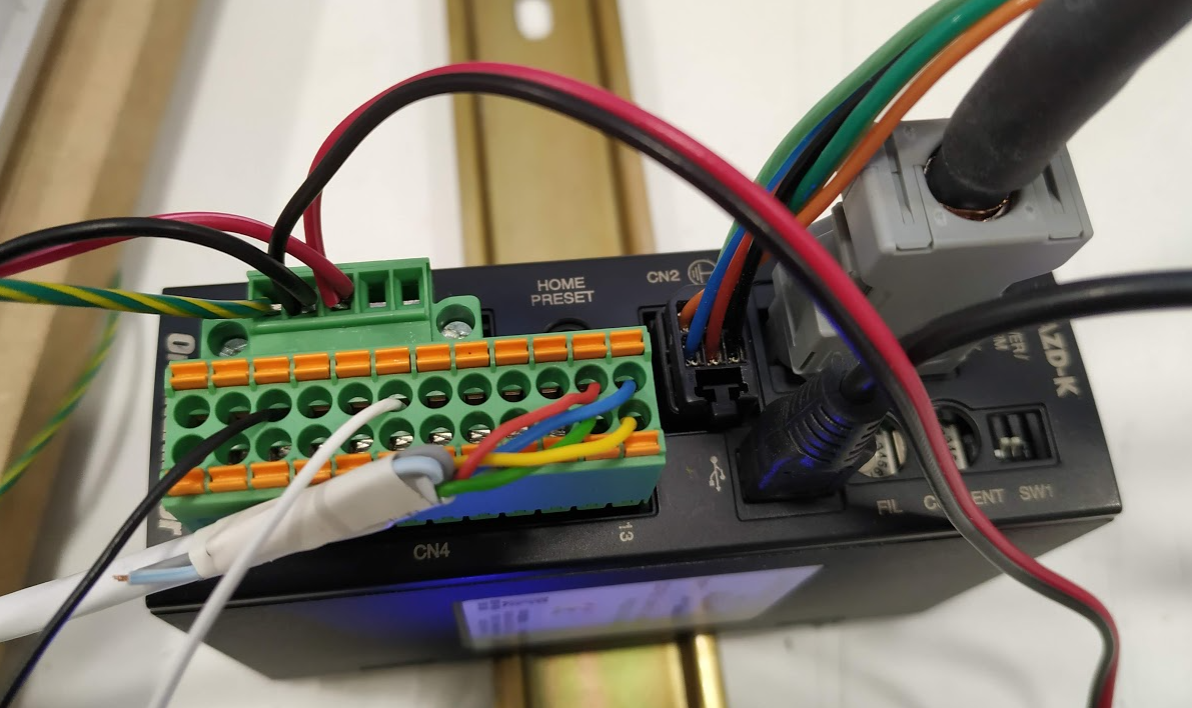
Homed at the driver:
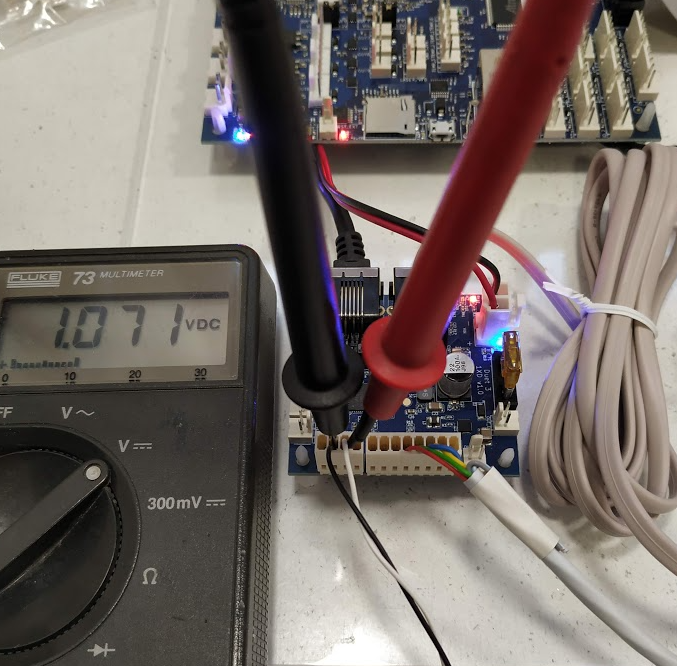
Away from home at the driver:
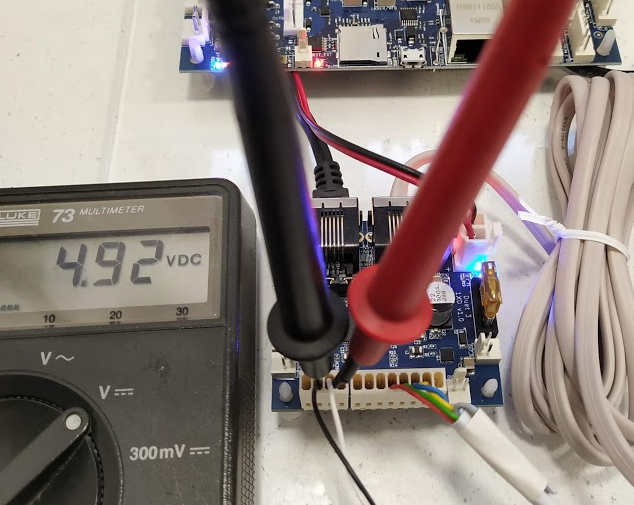
What I think is that these pins of the driver output do not draw voltage, they only draw current because it is like a switch. I don't know whether to inject 24v into the signal pin (white cable pin) in the driver (which tolerate it) to see if there is any change when adding voltage to the signal. It may be necessary to put a resistor to reduce the maximum current to reduce at 10mA or less.
The driver schematic for that pin is this:
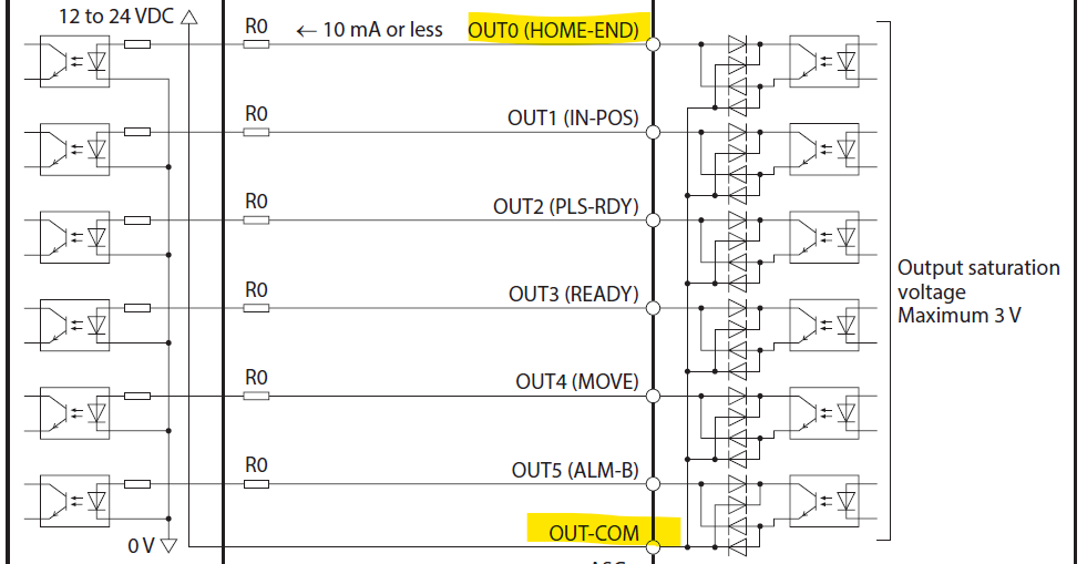
This at least is a leap forward, which gives me hope that it can work.