Request Cartesian with cyclops system: 2 extruders and 1 hotend
-
@FelixH said in Request Cartesian with cyclops system: 2 extruders and 1 hotend:
M563 P1 D1 H1 ; Define tool 1
I think the problem is that you have a second extruder drive defined in the tools, but you don't actually have a second extruder drive defined anywhere else.
@FelixH said in Request Cartesian with cyclops system: 2 extruders and 1 hotend:
M350 X16 Y16 Z16 E16 I1 ; Configure microstepping with interpolation M92 X100.00 Y100.00 Z400.00 E408.3 ; Set steps per mm M566 X600.00 Y600.00 Z18.00 E300.00 ; Set maximum instantaneous speed changes (mm/min) M203 X10000.00 Y10000.00 Z1000.00 E3600.00 ; Set maximum speeds (mm/min) M201 X1500.00 Y1500.00 Z100.00 E10000.00 ; Set accelerations (mm/s^2) M906 X650.00 Y800.00 Z800.00 E800.00 I30 ; Set motor currents (mA) and motor idle factor in per cent
-
I've just added the additional settings for the second extruder and still doesn't seem to work. On the web interface I cannot use the second extruder either.
I don't think the PanelDue is to blame, but just for the sake of being up to date, I will update everything tomorrow
-
@FelixH said in Request Cartesian with cyclops system: 2 extruders and 1 hotend:
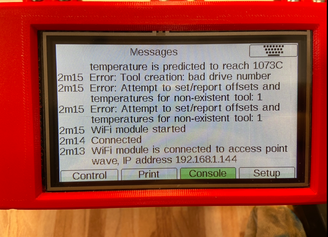
Tool creation: Bad drive number
Do you still get the same error message after adding the drive details?
The second drive would only be active when the second tool is selected. How are you trying to control it?
-
It is still not recognizing the additional tool. I was trying to select it by sending T1 to the console, which only greys-out the extrude/retract buttons on the web interface (even though I allowed cold extrusion).
I made a picture of the console on the panelDue:

-
UPDATE: just updated to 3.2.2 and nothing changed
-
Can you try copy and pasting the config sample I posted and trying that?
-
Just did, no change.
At this point I am wondering if it is at all possible a hardware error, like a bad crimped cable or something like that.
-
Is it still giving error messages like shown on the paneldue?
-
Yeah, but I have a new lead. Hold on
-
So, when I turn on the printer a whole lot of error codes flashed on the PanelDue screen. It was so fast, I had to recorded with my phone with the Slow-Mo option. The errors are as follows:
Error in the macro file line 32 column 32: M350 array too long, max length = 1
Error in the macro file line 33 column 34: M92 array too long, max length = 1
Error in the macro file line 34 column 34: M566 array too long, max length = 1
Error in the macro file line 35 column 41: M203 array too long, max length = 1
Error in the macro file line 36 column 35: M201 array too long, max length = 1
Error in the macro file line 37 column 35: M906 array too long, max length = 1
So I checked the documentation and I changed this snipped:
M350 X16 Y16 Z16 E16:16 I1                        ; Configure microstepping with interpolation
M92 X100.00 Y100.00 Z400.00 E408:408          	  ; Set steps per mm
M566 X600.00 Y600.00 Z18.00 E300:300         	  ; Set maximum instantaneous speed changes (mm/min)
M203 X10000.00 Y10000.00 Z1000.00 E3600:3600 	  ; Set maximum speeds (mm/min)
M201 X1500.00 Y1500.00 Z100.00 E10000:10000 	  ; Set accelerations (mm/s^2)
M906 X650.00 Y800.00 Z800.00 E800:800 I30  	  ; Set motor currents (mA) and motor idle factor in per cent
for this one:
M350 X16 Y16 Z16 I1                  		      ; Configure microstepping with interpolation
M350 E16:16                        				  ; Configure microstepping with interpolation
M92 X100.00 Y100.00 Z400.00                 	  ; Set steps per mm
M92 E408:408          	                          ; Set steps per mm
M566 X600.00 Y600.00 Z18.00         	          ; Set maximum instantaneous speed changes (mm/min)
M566 E300:300         	                          ; Set maximum instantaneous speed changes (mm/min)
M203 X10000.00 Y10000.00 Z1000.00 	              ; Set maximum speeds (mm/min)
M203 E3600:3600 	                              ; Set maximum speeds (mm/min)
M201 X1500.00 Y1500.00 Z100.00 	                  ; Set accelerations (mm/s^2)
M201 E10000:10000 	                              ; Set accelerations (mm/s^2)
M906 X650.00 Y800.00 Z800.00 I30  	              ; Set motor currents (mA) and motor idle factor in per cent
M906 E800:800 I30  	                              ; Set motor currents (mA) and motor idle factor in per cent
Unfortunatelly, however. Nothing changed.
-
I have no M584 command. I think that's it. Going to see the documentation.
UPDATE: so, that was it. I had no M584 mapping command. I read it completely by chance while reviewing the M305 command... Anyway now it works as I expected on both the web interface and the PanelDue display.
Thanks for sticking with me @Phaedrux
-
If somebody lands on this thread looking for the same info as I was, here you have it. This is what did it after some headaches:
; Configuration file for Duet WiFi (firmware version 3.11) ; executed by the firmware on start-up ; ; generated by RepRapFirmware Configuration Tool on Mon Feb 04 2019 17:03:09 GMT+0100 (Central European Standard Time) ; General preferences G90 ; Send absolute coordinates... M83 ; ...but relative extruder moves ;Panel Due Setup M575 P1 B57600 S1 ; Network M550 P"FH-Dual" ; Set machine name M552 S1 ; Enable network M586 P0 S1 ; Enable HTTP M586 P1 S0 ; Disable FTP M586 P2 S0 ; Disable Telnet ; Drives M569 P0 S1 ; Drive 0 goes forwards M569 P1 S1 ; Drive 1 goes forwards M569 P2 S0 ; Drive 2 goes forwards M569 P3 S1 ; Drive 3 goes backwards M569 P4 S1 ; Drive 4 goes backwards M584 X0 Y1 Z2 E3:4 ; Driver 0 controls the X motor, 1 controls Y, 2 controls Z motors, 3 and 4 control E motors M350 X16 Y16 Z16 I1 ; Configure microstepping with interpolation M350 E16:16 ; Configure microstepping with interpolation M92 X100.00 Y100.00 Z400.00 ; Set steps per mm M92 E408:408 ; Set steps per mm M566 X600.00 Y600.00 Z18.00 ; Set maximum instantaneous speed changes (mm/min) M566 E300:300 ; Set maximum instantaneous speed changes (mm/min) M203 X10000.00 Y10000.00 Z1000.00 ; Set maximum speeds (mm/min) M203 E3600:3600 ; Set maximum speeds (mm/min) M201 X1500.00 Y1500.00 Z100.00 ; Set accelerations (mm/s^2) M201 E10000:10000 ; Set accelerations (mm/s^2) M906 X650.00 Y800.00 Z800.00 I30 ; Set motor currents (mA) and motor idle factor in per cent M906 E800:800 I30 ; Set motor currents (mA) and motor idle factor in per cent M84 S30 ; Axis Limits M208 X0 Y-49.0 Z0 S1 ; Set axis minima M208 X220 Y209 Z200 S0 ; Set axis maxima ; Endstops M574 X1 S3 ; Motor Stall X Endstop M574 Y1 S3 ; Motor Stall Y Endstop M915 X Y S30 F0 R0 ; Stall guard config when not homing M574 Z1 S2 ; Set endstops controlled by probe M558 P5 C"zprobe.in" I1 H5 F300 T6000 ; Set Z probe type to switch and the dive height + speeds G31 P500 X-23 Y7 Z0.35 ; Set Z probe trigger value, offset and trigger height ; The larger the number the closest it gets to the bed ; i.e. 1.50 puts the nozzle closer to the bed than 1.20 M557 X40:210 Y5:190 S20 ; Define mesh grid ; Bed Heaters/Thermistors M308 S0 P"bedtemp" Y"thermistor" T100000 B4092 C0 R4700 ; Define thermistor M950 H0 C"bedheat" T0 ; Link pin name with heater M307 H0 B0 S1.00 ; Disable bang-bang mode for the bed heater and set PWM limit M140 H0 ; Links everything on the GUI M143 H0 S95 ; Set temperature limit for heater 0 to 95C ; HotEnd Heaters/Thermistors M308 S1 P"e0temp" Y"thermistor" T103944 B3943 C1.658e-7 R4700 ; Define thermistor M950 H1 C"e0heat" T1 ; Link pin name with heater M143 H1 S290 ; Set temperature limit for heater 1 to 290C ; Bed / HotEnd Autotunes M307 H1 A1048.7 C250.3 D10.3 V24.1 B0 ; Hotend Autotune //Changed M307 H0 A112.6 C601.0 D1.0 V24.1 ; Bed Autotune //Changed ; Fans M950 F0 C"fan0" Q500 M106 P0 S0 H-1 ; Set fan 0 value, PWM signal inversion and frequency. Thermostatic control is turned off M950 F1 C"fan1" Q500 M106 P1 S1 H1 T45 ; Set fan 1 value, PWM signal inversion and frequency. Thermostatic control is turned on ; Set fan 1 value, PWM signal inversion and frequency. Thermostatic control is turned on ; Tools M563 P0 D0 H1 ; Define tool 0 M563 P1 D1 H1 ; Define tool 1 G10 P0 X0 Y0 Z0 ; Set tool 0 offsets G10 P0 S0 R0 ; Set tool 0 operating and standby temperatures G10 P1 X0 Y0 Z0 ; Set tool 1 offsets G10 P1 S0 R0 ; Set tool 1 operating and standby temperatures ; Automatic power saving M911 S10 R11 P"M913 X0 Y0 G91 M83 G1 Z3 E-5 F1000" ; Set voltage thresholds and actions to run on power loss ; Custom settings are not configured T0 T1 -
-
@Phaedrux
Just out of curiosity, now that the drive mapping is added, would it still be necessary to have separate jerk-, acceleration-, etc- setting for the second extruder?
Is it even possible to have different settings?[OT]
Like different steps/mm for a geared direct drive mixed with a remote Bowden extruder?

-
I will try to see if it still works if it has only half of the settings. I have no idea...
Why wouldn‘t be possible to have different settings? What would be the point to have the possibility to set two settings if it wasn‘t?
-
@FelixH
Right, it's just a bad gutt feeling.
I remember, some settings had to be identical or be ignored if you set them different. -
I've just checked. You can set separate settings. Actually I've just done it for the M92 command
-
@FelixH said in Request Cartesian with cyclops system: 2 extruders and 1 hotend:
What would be the point to have the possibility to set two settings if it wasn‘t?
Imagine a Z-axis driven by three different steppers...not a common thing, but I believe it's related to the drive mapping.
When you define eg. M584 Z3:4:5, there are limits, of what you can specify later.
Same for mixing hotends IIRC. -
@o_lampe said in Request Cartesian with cyclops system: 2 extruders and 1 hotend:
Just out of curiosity, now that the drive mapping is added, would it still be necessary to have separate jerk-, acceleration-, etc- setting for the second extruder?
Is it even possible to have different settings?Yes. Extruders are considered as independent axis and should have all settings defined for each extruder and those settings can be different.
For other axis like XYZ you only need a single value for that axis. You must use identical motors for axis with multiple motors and you cannot have different settings for each motor.
See the notes here: https://duet3d.dozuki.com/Wiki/Gcode?revisionid=HEAD#Section_M584_Set_drive_mapping
