Distribution & Toolboard connection Problems
-
Is the fuse on the tool board for that output intact?
-
@dc42 Do you mean the Fuse on the Tool Distribution Board ?
It is ok. I also tried another Port, but the same. No LEDs or other signs of life
Regards Frederik
-
I suggest you use a multimeter to check that you have +24V on the +VIN pin of the VIN connector on the tool board with respect to the ground pin.
-
@dc42 I checked it, 24V is ok on the tool and distribution board. Polarity is correct
-
@dc42 i used a stright trough 4 pin can cable
-
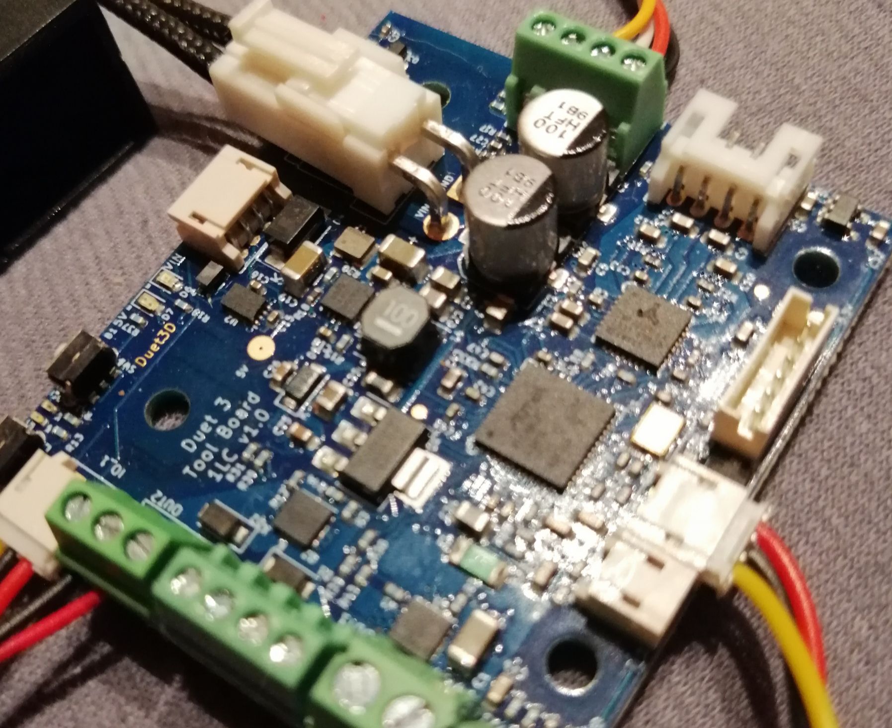
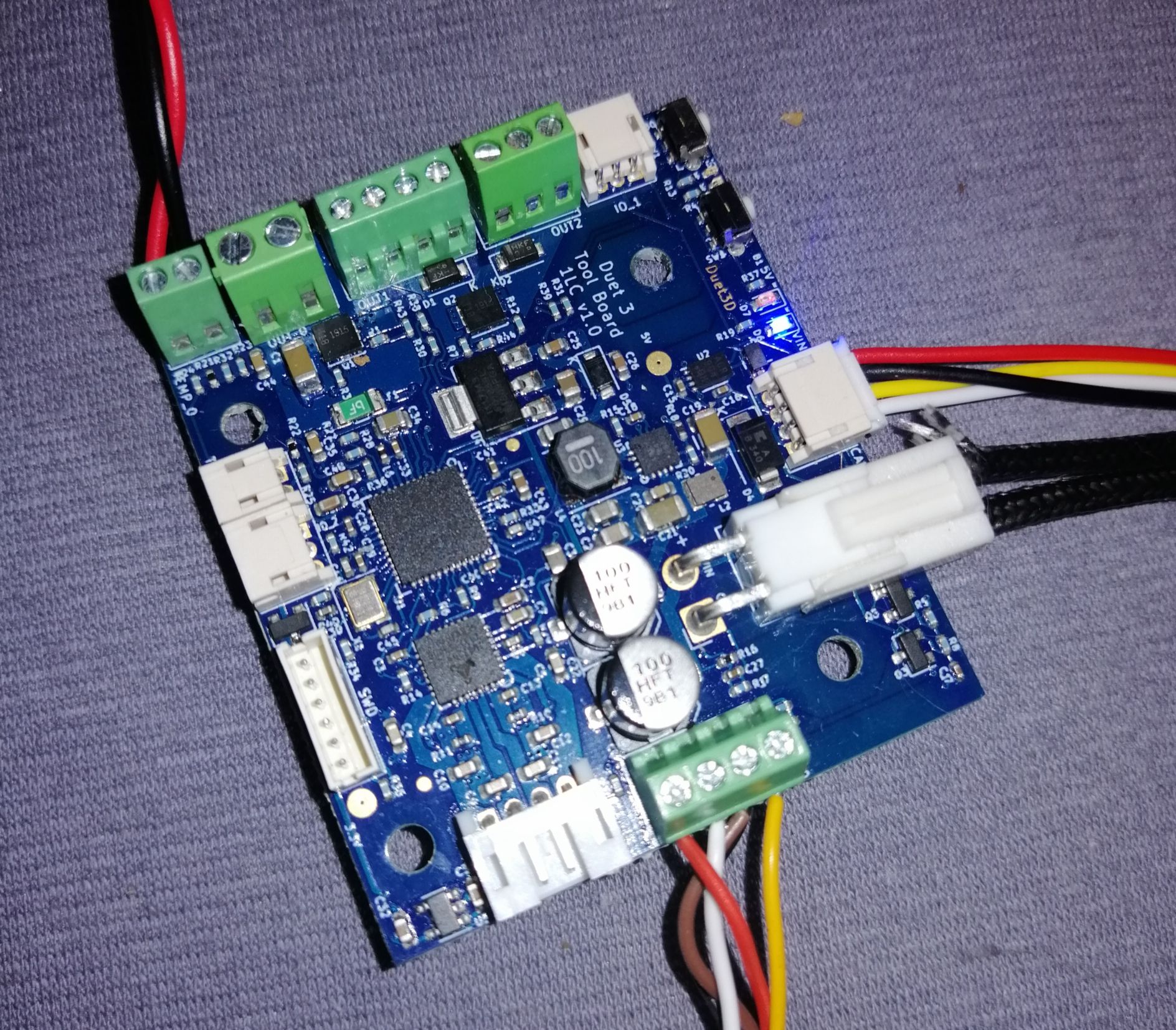
Even without the CAN cable, with VIN power applied to the tool board you should get 2 LEDs lit and another one flashing. Please post photos showing how 24V power is supplied to VIN on the tool board.
-
@dc42 as soon as i am back from Work, i will post pictures.
-
@dc42 I supplied the Vin direct from my 24v power supply to the Vin of the tool distribution board. And from there with the first port to the toolboard lc1. I need 2 more hours at my office. I will send you the pictures as soon as I am at home. Could I test some other parts with my multimeter to check the correct function?
Regards
Frederik -
I checked the connections and fuses with the multimeter. Everything ok. 24.1v on the toolboard. But no led are on.!

-

-
@dc42 Thank you, Problem Solved.
I rewired the distro and toolboard + making new crimps for my vin cables.i was measuring the 24v on the bottom of the connector and checked the polarity.
But somehow the connection made no contact to the toolboard.when plugged in
I also updated my duet3 to RRF 3.2beta4.1now the blue led is on and the red led is constantly on like the diag led on the duet 3, but not flashing. Is the firmware wrong?
What is the next thing to check?
Pressing the 2 buttons while starting the board doesn't change the led signals.Is there another way to reset the toolboard and check the CAN connection?
Regards
Frederik
-
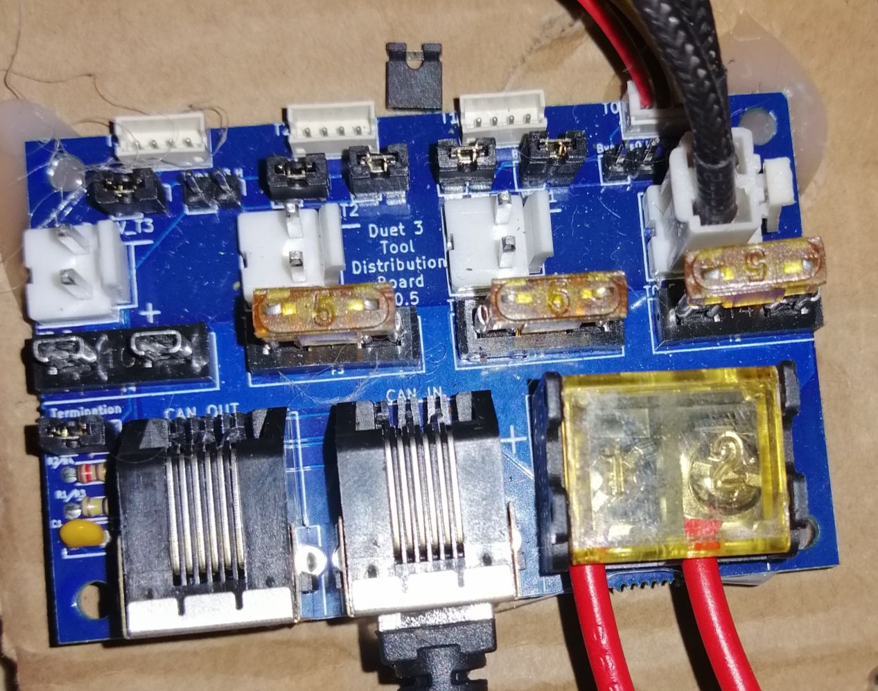
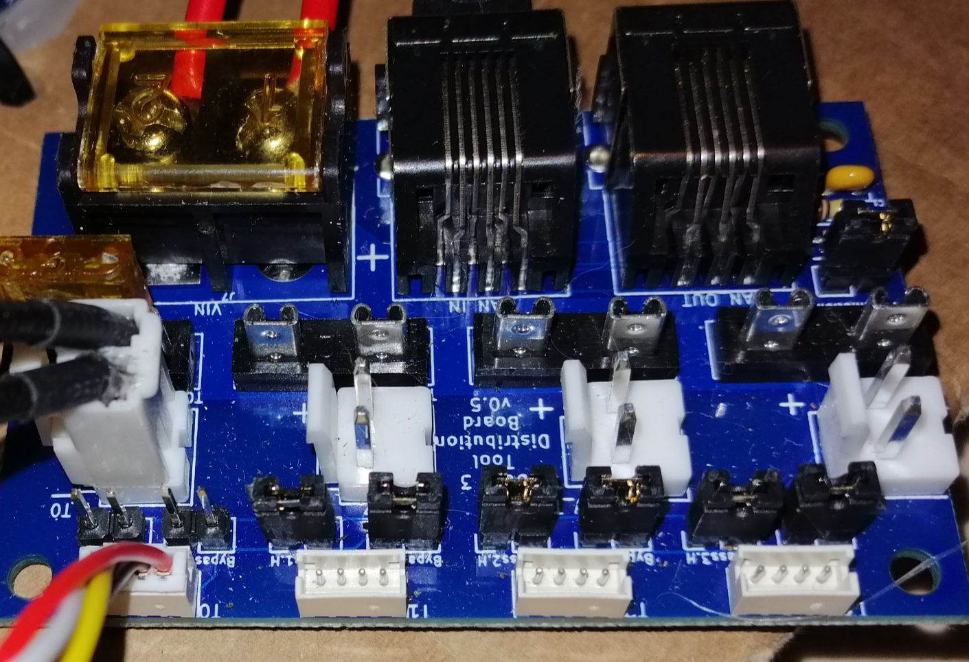
it might not matter, but the tool distribution board you showed is missing a bypass jumper on the 4th unused output and doesn't show the jumper for the 1st you're actually using.
-
@bearer thanks for pointing that out. I uploaded the wrong photo. The jumpers are both removed from the first port with the cable and are set in every else slot.

I test both ways. With only one of the two jumpers removed and both jumpers removed. The same result in the console and no change in led behavior.
-
M122 === Diagnostics === RepRapFirmware for Duet 3 MB6HC version 3.2-beta4 running on Duet 3 MB6HC v1.01 or later (SBC mode) Board ID: 08DJM-956BA-NA3TN-6J9DL-3S46S-99AUT Used output buffers: 1 of 40 (11 max) === RTOS === Static ram: 123212 Dynamic ram: 138092 of which 24 recycled Never used RAM 130864, free system stack 200 words Tasks: Linux(ready,101) HEAT(blocked,298) CanReceiv(blocked,947) CanSender(blocked,371) CanClock(blocked,356) TMC(blocked,54) MAIN(running,1189) IDLE(ready,19) Owned mutexes: HTTP(MAIN) === Platform === Last reset 00:01:10 ago, cause: power up Last software reset at 2020-12-10 01:00, reason: User, GCodes spinning, available RAM 130864, slot 2 Software reset code 0x0003 HFSR 0x00000000 CFSR 0x00000000 ICSR 0x0044a000 BFAR 0x00000000 SP 0xffffffff Task Linu Error status: 0x00 MCU temperature: min 26.1, current 35.2, max 35.3 Supply voltage: min 24.0, current 24.1, max 24.2, under voltage events: 0, over voltage events: 0, power good: yes 12V rail voltage: min 12.1, current 12.1, max 12.2, under voltage events: 0 Driver 0: position 0, standstill, reads 21528, writes 14 timeouts 0, SG min/max 0/0 Driver 1: position 0, standstill, reads 21529, writes 14 timeouts 0, SG min/max 0/0 Driver 2: position 0, standstill, reads 21530, writes 14 timeouts 0, SG min/max 0/0 Driver 3: position 0, standstill, reads 21533, writes 11 timeouts 0, SG min/max 0/0 Driver 4: position 0, standstill, reads 21534, writes 11 timeouts 0, SG min/max 0/0 Driver 5: position 0, standstill, reads 21532, writes 14 timeouts 0, SG min/max 0/0 Date/time: 2020-12-10 06:17:24 Slowest loop: 0.90ms; fastest: 0.12ms === Storage === Free file entries: 10 SD card 0 not detected, interface speed: 37.5MBytes/sec SD card longest read time 0.0ms, write time 0.0ms, max retries 0 === Move === Hiccups: 0(0), FreeDm: 375, MinFreeDm: 375, MaxWait: 0ms Bed compensation in use: none, comp offset 0.000 === MainDDARing === Scheduled moves 0, completed moves 0, StepErrors 0, LaErrors 0, Underruns [0, 0, 0], CDDA state -1 === AuxDDARing === Scheduled moves 0, completed moves 0, StepErrors 0, LaErrors 0, Underruns [0, 0, 0], CDDA state -1 === Heat === Bed heaters = 0 -1 -1 -1 -1 -1 -1 -1 -1 -1 -1 -1, chamberHeaters = -1 -1 -1 -1 === GCodes === Segments left: 0 Movement lock held by null HTTP* is doing "M122" in state(s) 0 Telnet is idle in state(s) 0 File is idle in state(s) 0 USB is idle in state(s) 0 Aux is idle in state(s) 0 Trigger* is idle in state(s) 0 Queue is idle in state(s) 0 LCD is idle in state(s) 0 SBC is idle in state(s) 0 Daemon is idle in state(s) 0 Aux2 is idle in state(s) 0 Autopause is idle in state(s) 0 Code queue is empty. === CAN === Messages queued 158, send timeouts 510, received 0, lost 0, longest wait 0ms for reply type 0, free buffers 47 === SBC interface === State: 0, failed transfers: 0 Last transfer: 19ms ago RX/TX seq numbers: 1334/1335 SPI underruns 0, overruns 0 Number of disconnects: 0, IAP RAM available 0x20a28 Buffer RX/TX: 0/0-0 === Duet Control Server === Duet Control Server v3.2.0-beta4 Code buffer space: 4096 Configured SPI speed: 8000000 Hz Full transfers per second: 0.11 -
M997 B121 S3
Error: M997: Response timeout: CAN addr 121, req type 6024, RID=14
everything I try only generates this timeouts. M115, M122, M997... Are there other parts to test with the multimeter to ensure that I got a working unit?
-
@Frederik said in Distribution & Toolboard connection Problems:
Messages queued 158, send timeouts 510,
this would indicate that there is something wrong with your can wiring.
-
@Veti I use a straight through 4 pin can cable that I made with the lc1 connector pack
-
have you done the simple setup and tested that?
https://d17kynu4zpq5hy.cloudfront.net/igi/duet3d/IgXsNbOKcEAWjeNO.huge
also check the continuity of your can wiring. a bad crimp here will also be a headache.
-
@Veti I would try if I'd had a 120ohm resistor and a spare rj11 cable at Hand. I can source a bunch of those resistors later at my local electro shop.
-
@Veti i checked for continuity with the multimeter. Seems to be OK