Connecting a 12V PWM FAN when using a 24V power supply
-
@dc42
could you run a wire from the 12V output on the duex to the v_fan pin on the duet to make the duet fans ports 12v as well? -
@Veti said in Connecting a 12V PWM FAN when using a 24V power supply:
@dc42
could you run a wire from the 12V output on the duex to the v_fan pin on the duet to make the duet fans ports 12v as well?Yes that would work too.
-
@dc42 Thnx for the answer. They're indeed noctuas. I say go ugly brown or go home

So just to be sure and not blow anything up:
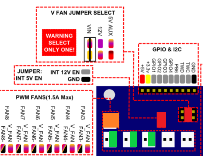
- I have a duex2 0.8

- 2x Red jumper
- 1x Orange for 12V +/- all fans, PWM disabled (couldn't find a 12V out)
- 3x green the PWM lead for the fan
- 3x ? where would the tacho lead go? GPIO 1-3
Please let me know if that would be ok.
Also why does the documentation note only to enable 12V if you use it. Is there a risk in enabling it?
- I have a duex2 0.8
-
Alright so against my better judgement I decided to test somethings out.
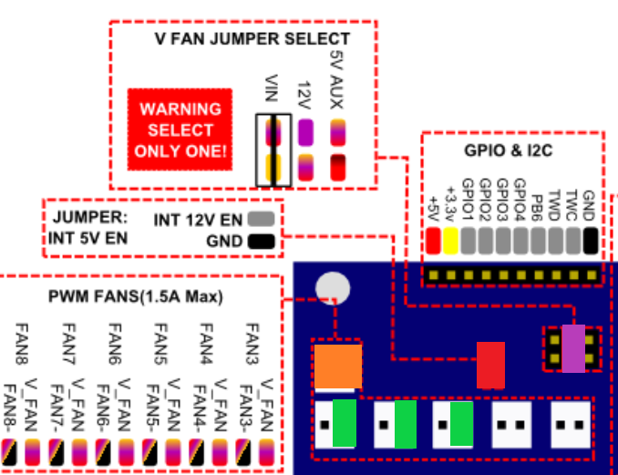
From what I tested the jumper makes the fan output 12V, jay! I have revised my plan of approach:

1x orange is now nothing!
1x red Jumper
1x purple 12V+ for FANs + a wire to short the two pins
3x green PWM signal
1x ground directly to ground of fans
3x tacho still not sure which inputs I can use on duex2 -
Alright, so another update couldn't leave it alone. I can confirm the Noctua runs like a charm. The above image green connections are incorrect! They need to be on FAN-
Now the only open point is the tacho, I don't really think I need it actually. What would be the benefit of connecting it?
-
you can see how fast they are spinning.
-
@Veti which input on the duex can I use for that. The forum names a input on the duet through the extension cable only.
-
you can find PB6 onn the GPIO and I2C header on the duex
-
@Veti does that mean you can only connect one tacho?
-
on the duet2 yes
edit: actually i am not sure if its possible with rrf3 to use additional ones