Logic Level shifter for 12864 display on Duet 2 Wifi
-
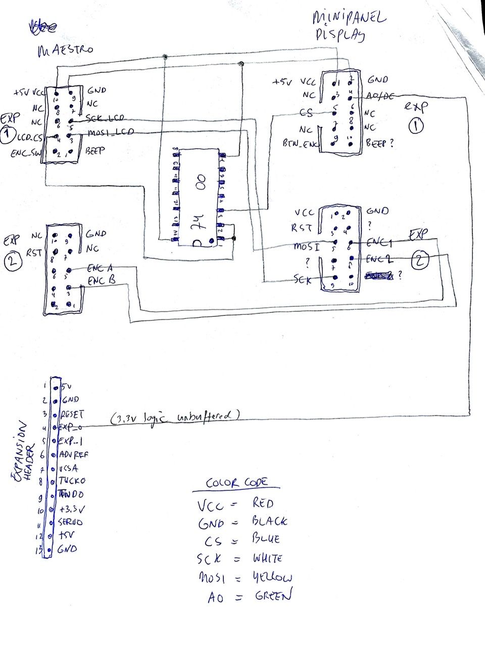
@antlob These are the pinouts and mapping I used with the 12864 MiniPanel on my printer.

Note that sometimes the plastic connector housing is reversed on displays, and the tab goes to the other side.
Edit: diagram updated the 7400 NAND gate and wiring.
-
@dc42 said in Logic Level shifter for 12864 display on Duet 2 Wifi:
That's the stepper channel 10 & 11 connector?
At least I'm not using reset, and apparently that display doesn't need it.
Maybe it makes sense to look at the pinout of the two connectors from the display you have and merge that into one connector, or at least have as many labels in the same place. But what I'm seeing is that there isn't much consistency between display manufacturers (looking at https://wiki.fysetc.com/Mini12864_Panel and the CR-20 display pinout).
-
@Schmart, thanks for the explanation. I hadn't got as far as reading the ST7567 datasheet enough to appreciate the differences other than the I/O interface differences.
We are short of flash memory space in the Duet WiFi/Ethernet firmware, so I am somewhat alarmed at how much extra code is needed to support both displays. I'm wondering whether it would be better to support only the ST7567 displays on these Duets, to keep the code size down and to minimise the extra hardware needed. In which case, the image bitmap could be organised as columns instead of as rows. This would probably be more efficient, because the character data in the fonts is organised as columns too.
-
@Schmart Thanks, maybe this is a stupid question but, since I have de LCD 12864 and not the Mini LCD 12864, Does the pinout of EXP1 and EXP2 is the same? Meaning that if I wire as you say (waiting for your final schematic) Will it work? Or just follow the original schematic at the top of this forum discussion. My problem is that I do not dare to compile the dev 3.02 since I know it will be a mess for me with a very low chace of success and I'm waiting for @dc42 to upload a 3.2 Alpha version. On the other hand I also have doubts about the correct schematic. If I run into trobule I do not have the skill nor the knowledge to solve it. I'm sorry that I cannot be of any help, believe that if I could I'll do it. Guess I have to wait.
-
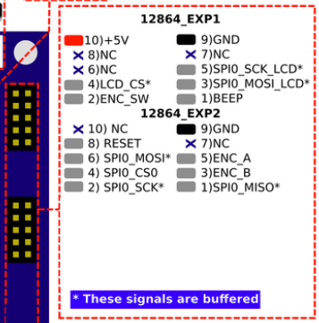
@antlob Certainly not a stupid question. If you have a regular RepRapDiscount graphics display, with a ST7920 on it (or a BigTreeTech TFT24 with ST7920 emulation) then the pinout I'm showing you is very likely completely different, so wiring like in my schematic will not work. I think the pinout should instead be similar or identical to the connectors of the Maestro (shameless grab from the schematic):

Do you have some pictures of the front and back of your display?
-
@dc42 I know the 12864 changes were a tight fit for the Duet Wifi/Ethernet already and that you were really looking to shave those last bytes off.
Is there a way I can determine which functions or constructs primarily contribute to the firmware size growth?
I haven't looked at optimizing my code (or any code actually) yet, but I also noticed that functions like DrawCircle() and ReadPixel() are not used at the moment. We can probably disable these with a
#define. And I wanted to optimize the Flush() routine even more anyway because there are still enough similarities between the ST7920 and ST7565 with respect to flushing logic. I'm just not certain in how many bytes I can save there.To your idea of making a ST7565 specific build; in the existing code, a fair number of functions use the display buffer directly, so using the buffer with a rotated orientation would require careful checking and possibly abstracting these functions from accessing the buffer directly. That's some work, but still feasible, and perhaps something to do anyway because I have a hunch this might even save some code.
-
I updated the schematic of how I hooked up my MiniPanel display to the Maestro. See a couple of posts above.
-
@Schmart said in Logic Level shifter for 12864 display on Duet 2 Wifi:
but I also noticed that functions like DrawCircle() and ReadPixel() are not used at the moment
The linker eliminates any non-virtual functions that are not referenced, so no need to disable them using #define.
-
I've been working on the code in RRF 3.2 to vary the number of drivers depending on whether a display is configured or not. In the process, I finalised the pin assignments for Duet WiFi to the Fysetc mini 12864 display, as follows.
constexpr Pin EncoderPinB = PortCPin(7); // connlcd.3 -> exp2.6 constexpr Pin EncoderPinA = PortAPin(8); // connlcd.4 -> exp2.8 constexpr Pin LcdNeopixelPin = PortDPin(18); // connlcd.5 -> exp1.5 constexpr Pin LcdResetPin = PortCPin(28); // connlcd.6 -> exp1.6 constexpr Pin LcdA0Pin = PortDPin(19); // connlcd.7 -> exp1.7 constexpr Pin LcdCSPin = PortAPin(25); // connlcd.8 -> exp1.8 constexpr Pin EncoderPinSw = PortDPin(20); // connlcd.9 -> exp1.9 constexpr Pin LcdBeepPin = PortDPin(21); // connlcd.10 -> exp1.10 // Additional spi wiring for FYSETC Mini 12864 display: // connlcd.2 (gnd) -> exp1.2 // connsd.1 (+5V) -> exp1.1 // connsd.2 (gnd) -> exp2.2 // connsd.3 (SD CS) -> exp2.7 // connsd.4 (sck) -> exp2.9 // connsd.5 (mosi) -> exp2.5 // connsd.6 (miso) -> exp2.10 -
Sounds promising. I have one of these displays gathering dust
-
Hi @dc42
I've optimized and simplified the code further in my repo and managed to save a few hundred bytes.
Also, the ST7565 display now works without additional logic components, inverting the LCD_CS with a 74xx00 is not necessary anymore. I've used the exp_0 pin for DC and the exp_1 pin for CS now. My display accepts the logic levels perfectly.
I should be able to save another 60 bytes or so, but I have to first work out an issue that I uncovered when I start drawing columns pixel by pixel.
-
@Schmart where'd one find your patch, and what does the new wiring look like? Inquiring minds want to know ...
-
@dc42: I created a pull request of my changes today, and I tested:
- ST7920 display type 1
- ST7565 display type 2 that uses EXP_1 for active low CD
- ST7565 display type 3 which needs a NAND inverter IC to invert the LCD_CS towards the display
Also implemented a couple of optimizations, solved a few bugs and simplified the Flush routine.
I see some room for further size reduction of the firmware, but that would probably make some parts of the code a little slower. What's your stance on that?
-
Hi @oliof, back from fishing?

The changes are in the following repo and branch.
https://github.com/SchmartMaker/RepRapFirmware/tree/ST7565I have a binary firmware for the Maestro here:
https://1drv.ms/u/s!Au1g8fW6BaQzioADewiHDAxzQ_Adlg?e=KuNYOBWhat's the board you're using? I'm asking, because the firmware build for the Duet Wifi and Duet Ethernet is still a little too large for the flash memory of these boards unfortunately.
-
@oliof I'll see if I can hack the wiring picture so that it reflects the new option that doesn't require the 74xx00.
-
I have a Duet2Wifi, but I can easily remove stuff I don't need (I did remove Hangprinter when trying the level shifter approach).
-
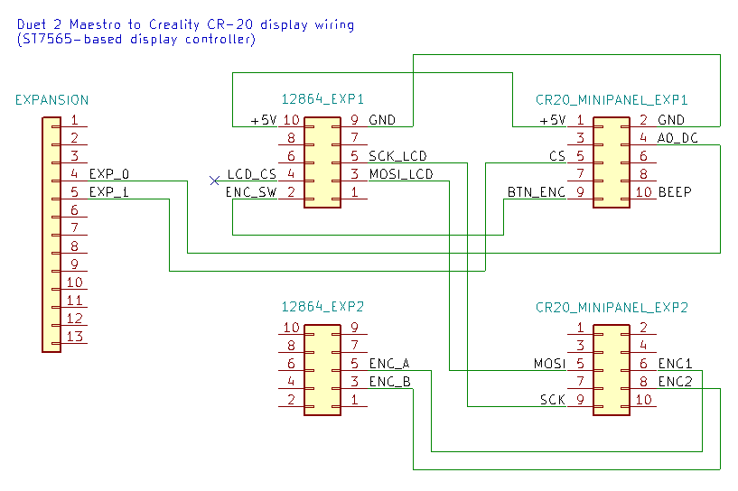
@oliof This is the wiring I used without the inverter.
So to be clear and safe, this is very specific wiring to connect the Duet 2 Maestro to a Creality ST7565-based MiniPanel display @3.3v logic levels.
The pinout of displays made vary wildly, and the connectors on display-side may need to be reversed (the plastic shroud rotated 180 degrees). Also, the firmware adaptations I made in my fork are relatively easy to change for the Duet 2 Wifi, but I believe you would need to make changes in the Pins.h specific to the board and maybe also in Display.cpp (for now).

Edit: Since @oliof is using the exact same Creality MiniPanel display from the CR-20, I have adjusted the diagram to match the exact orientation of the display connectors on that specific display. The tab goes on the side of pin #1.
-
@Schmart said in Logic Level shifter for 12864 display on Duet 2 Wifi:
The pinout of displays made vary wildly, and the connectors on display-side may need to be reversed (the plastic shroud rotated 180 degrees). Also, the firmware adaptations I made in my fork are relatively easy to change for the Duet 2 Wifi, but I believe you would need to make changes in the Pins.h specific to the board and maybe also in Display.cpp (for now).
I have a Creality minipanel I want to use, so we're in the clear there. I'll check how Pins.h need to be adapted if I get around to it before this lands in 3.2 or beyond.
-
@oliof That would be so cool if you'd get it working as well. I'm not at my computer anymore, but I believe I'm using ‘M918 P2 E4 F2000000‘ in my config.g.
-
Please note, the wiring diagram posted by @Schmart above is not the wiring arrangement that will be supported in RRF 3.2. The wiring arrangement in 3.2 is listed in this post https://forum.duet3d.com/post/157139.