New power output for toolboard
-
Hello, may I have some help to control a new power output on duet3 Tool Board 1LC v0.6 for a second heating element?
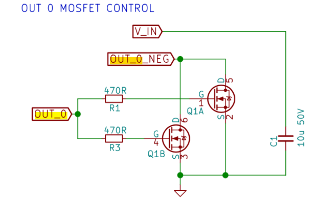
I build a mosfet darlington based on OUT_0 in toolboard schematic and connected to the tool board ATSAMC21G18A pin PA16(25).
My question is, how can I address this pin and add a function to it?

Thank you for the help.
-
You would need to change the line for PA16 in file src/Config/TOOL1LC_V06.h. Giving the pin a name such as "out3" should be sufficient.
If the pin is intended for a heater, you might want to add a 10K pulldown resistor between PA16 and ground, to ensure that the mosfets are off when the board starts up. We've added a similar resistor on OUT_0 in later production tool boards.
-
Thank you @dc42, I'll give it a try. I'll add the 10k pulldown for OUT_0 as well.
I look up but did not find the kicad pcb design on git. It is exist? I'll looking for a better trace for add the resistors than the uC pin.
-
@dc42 there is an opportunity to drive an RC servo (PWM) from the toolboard? I can modify it and connect to the uC pin if needed.
-
@eduard said in New power output for toolboard:
@dc42 there is an opportunity to drive an RC servo (PWM) from the toolboard? I can modify it and connect to the uC pin if needed.
The IO_0_OUT pin is PWM capable, it already gets used to control a BLTouch. However, the on-board 5V regulator doesn't have much spare output capacity, so a servo will need external 5V power. Additionally, when servos decelerate they pump energy back into the power rail, which causes the voltage to rise; and this could easily damage the microcontroller if you powered the servo from the tool board.
-
@eduard said in New power output for toolboard:
I look up but did not find the kicad pcb design on git. It is exist? I'll looking for a better trace for add the resistors than the uC pin.
PCB layout is not on github yet. I checked in KiCad and there are no traces connected to any of the unused pins 25-28 of the MCU. I've made a note to add pads for one or more of these pins in the next PCB revision.
-
Thank you for your answer, I'll keep in mind while designing the servo control pcb. Perhaps a supressor diode will do the job.
How can I drive the servo from G-code? The is already a macro for servo drive? (0-180 degree control, or mapping command)
-
@eduard said in New power output for toolboard:
How can I drive the servo from G-code? The is already a macro for servo drive? (0-180 degree control, or mapping command)
See the M280 command.
-
Great, thank you!