CR10v2 - Duet 3 Connections - Part 2
-
@bearer said in CR10v2 - Duet 3 Connections - Part 2:
Include M122with wiring as is
Not 100% sure what you mean by this.
Weird the number of drivers for the different error change over timer; but just rule out something being wrong with the board - does it happen with no motors attached, and does the driver chips actually get warm?
I'll unplug the the drivers and see. I'll also check and see if the drivers were warm. I felt them earlier and they didn't seem warm.
Also see if M122 changes with motors disconnected. At a glance i couldn't see anything immediately wrong but will take a closer look in the morning if its not sorted by then. GL!
Not sure about this either!
Thanks for your help!
Pat
-
So I'm working on the fan(s)...
This is my current fan section of my config.g:
; Fans
M950 F0 C"out7" Q500 ; create fan 0 on pin out7 and set its frequency
M106 P0 S0 H-1 ; set fan 0 value. Thermostatic control is turned off
M950 F1 C"out8" Q500 ; create fan 1 on pin out8 and set its frequency
M106 P1 S1 H1 T45 ; set fan 1 value. Thermostatic control is turned onI have my part cooling fan plugged into out7 and it works. The code above says it is thermostatically controlled. Do I want that?
The Hotend cooling fan is plugged into out8 but it is not working. I think I want that always on or also thermostatically controlled so that when it gets to, maybe, 50 degrees, it will pop on.
I have a motherboard cooling fan that I want on all the time. I'm assuming it would go into out9. How would I code this to be on all of the time?!
Thanks, Pat
-
Have you paired the wires from each stepper motor into phases using a multimeter (there are other ways of doing it too) and checked that you have connected one phase to the 2 pins at one end of the motor connector, and one phase to the 2 pins at the other end?
The driver messages you are getting suggest that either you have got all the stepper motor connections not phased correctly, or your board ha as fault with SPI communication to the driver chips that only occurs after a few minutes. Do not change the stepper motor wiring order without checking the phases.
I have my part cooling fan plugged into out7 and it works. The code above says it is thermostatically controlled. Do I want that?
No, the part cooling fan should not be thermostatically controlled.
-
@BearcatTD for determining wire pairs, see https://duet3d.dozuki.com/Wiki/Choosing_and_connecting_stepper_motors#Section_Identifying_the_stepper_motor_phases
When commissioning, the sensible thing to do is connect one thing (eg one motor, one temp sensor, one fan) at a time, and test it. Connecting everything, flipping the on switch, then trying to troubleshoot, is asking for trouble.
Ian
-
@dc42 said in CR10v2 - Duet 3 Connections - Part 2:
No, the part cooling fan should not be thermostatically controlled.
Thanks! How do I do the coding in config.g for my three fans?
Part Cooling Fan out7
Hot end cooling fan out8
Motherboard cooling fan, I would assume out9Thanks again,
Pat -
@droftarts said in CR10v2 - Duet 3 Connections - Part 2:
When commissioning, the sensible thing to do is connect one thing (eg one motor, one temp sensor, one fan) at a time, and test it. Connecting everything, flipping the on switch, then trying to troubleshoot, is asking for trouble.
You got that right!! I'll take a run at the motor phase link
Thanks!
-
@BearcatTD said in CR10v2 - Duet 3 Connections - Part 2:
How do I do the coding in config.g for my three fans?
Part Cooling Fan out7
Hot end cooling fan out8
Motherboard cooling fan, I would assume out9You can always use the RRF config utility again, either in part (just fill in the bits you need), or in it's entirety (by loading the json file it produced the last time you used it; click 'Use existing configuration' on the start page, and it will prompt you to upload the json file). Using the first method, I get:
 ; Fans
M950 F0 C"out7" Q500                         ; create fan 0 on pin out7 and set its frequency
M106 P0 C"Part cooling fan" S0 H-1           ; set fan 0 name and value. Thermostatic control is turned off
M950 F1 C"out8" Q500                         ; create fan 1 on pin out8 and set its frequency
M106 P1 C"Hot end fan" S1 H1 T45             ; set fan 1 name and value. Thermostatic control is turned on
M950 F2 C"out9" Q500                         ; create fan 2 on pin out9 and set its frequency
M106 P2 C"CPU fan" S1 H-1                    ; set fan 2 name and value. Thermostatic control is turned off

; Tools
M563 P0 D0 H1 F1                             ; define tool 0
The part cooling fan and CPU fan are not thermostatically controlled. You can set the CPU fan to thermostatic control, and then tie that to the temperature monitoring of the CPU (setting this up is not supported in config tool) with:
M308 S2 Y"mcu-temp" A"MCU"         ; create sensor for mcu, shows on temp graph
M950 F2 C"out9" Q500               ; create fan 2 on pin out9
M106 P2 C"CPU fan" S1 H2 T45       ; set fan 2 name and value, use sensor 2
Not tested, but I think that should work.
Ian
-
@droftarts said in CR10v2 - Duet 3 Connections - Part 2:
You can always use the RRF config utility again,
do you know if anyone looked at how he ended up with mixed pin names for duet3 and duex5 initially? (from the configurator)
-
Thanks guys...Fans. Are. Working.
OK. Motor phases. I went through for each driver and phound the two wires that were in phase. Now I'm not quite sure what to do with them!
Thanks again!
-
@BearcatTD said in CR10v2 - Duet 3 Connections - Part 2:
Now I'm not quite sure what to do with them!
connect them ^^
one coil on the 1st and 2nd pin, the other coil on the 3rd and 4th pin. You can start on the left or the right, doesn't matter, if the motor turns the "wrong" way you can swap the coils or invert in config.
-
Thanks! Just so I'm hearing this right...
I would attach one of the "phase" wires to pin 1 or 2 and the other "phase" wire to pin 3 or 4. Does it matter which pins the other two wires go to ?
I apologize...this is probably maddening to you!
-

maybe that helps; keep the two wires that makes up a coil next to each other and it'll turn. if you got it "wrong" it'll just turn the "wrong" way, but lacking any standardized colour code or datasheet just wing it and change the direction in config after.
-
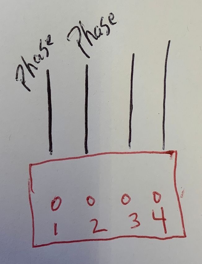
Bearer...I'm pretty thick. OK Here is a pretty picture I drew (my macbook croaked dead away this morning)

I'm not quite sure what constitutes a coil. So in the above image, this is what I originally had. So for attempt 1 I left pin one the same and I swapped pins 2 & 3. I got an error, "motor phase A may be disconected reported by driver(s) 2 3" Then the same error for phase B. For what is's worth, I also got "Failed to enable endstops", but we'll deal with that later.
Second attempt I swapped pins 1 & 3 and got the same errors.
I hope this makes sense... Thanks again for your time. I know you're in England, but I seriously owe you multiple beers!
-
@BearcatTD said in CR10v2 - Duet 3 Connections - Part 2:
in England
Lord no! (no offence to our British friends..)
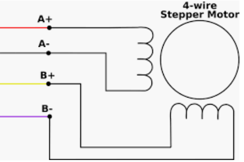
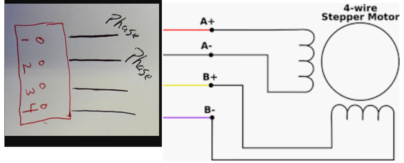
While I'm not sure what you refer to as a phase, lets try to assume we mean the same thing. if you measure a resistance between 1 and 2 on your drawing, it should be correct; the two other wires go on 3 and 4. You should not measure any resistance between 1&3, 1&4 and 2&4, just to eliminate any shorts in the motor.
If thats the case then we can put the two pictures together to try and see how it fits together.

-
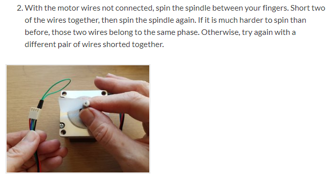
I think we're close. So the two wires labeled phase...This is where / how I found the two wires
https://duet3d.dozuki.com/Wiki/Choosing_and_connecting_stepper_motors#Section_Identifying_the_stepper_motor_phases

So knowing this, does that change the image above. Actually this is how I plugged the motor in which gave all of the "Short to ground" errors which are in the images at the top of the post.
Thanks again,Pat
-
it shouldn't change it no; as long as those are two wires that gives you the strongest braking effect, and you get the same with the other two.
unfortunately if that doesn't work when connected your options are the crimps are no good, or drivers are damaged (suppose it could be a configuration issue, but hard to say without the specs for the motor)