[SOLVED] Setup the 3rd (virtual) thermistor
-
Hi All ,
Still here to modify my printer. And as always I'll post in my 3d all the mods
Now , I'm connecting the mechanism of the hot chamber.
I have 3 thermistors:
1> head 1. (thermistor 01)
2> head 2. (I'm using a E3D heater for build the mechanism) (thermistor 02)
3> hot chamber (I would use the virtual thermistor 03 using the expansion pins)For configure the thermistor number 03 I read this 3d : https://forum.duet3d.com/topic/2098/multiple-combined-thermistors-for-a-single-tool-heatbed
And David talk about a 3rd pin to use in the wiring:
1)Positive thermistor plugged in the pin35
2)Negative thermistor plugged in the the VSSA pin (ground)
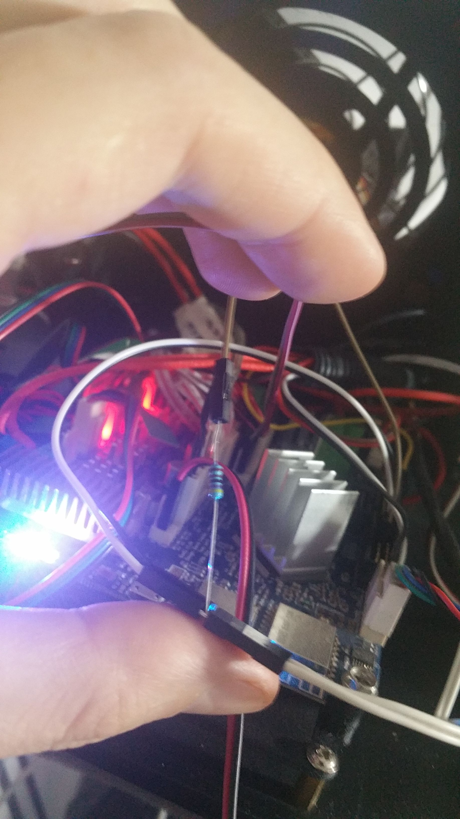
3)Plus a 4.7K between the ADVREF pin and the pin35. Is this last point correct?The configuration of my actual hot chamber sensors is this but I have to move it at the place of the thermistor 03 (pin35) :
;chamber thermal sensor -
M305 P2 T10000 ;
M143 H2 S100 ;
If I use that resistance (4.7K) in that way , the thermistor will still work properly?
Then , is possible control the heater 02 in function of the chamber temperature? If yes , how?
In case I would use also a 4rt thermistor I should use the same schematic sharing the VSSA pin and the ADVREF pin?
Many thanks for the attention

-
up!
No one can confirm this? I would not fry the board

-
Ok, I dare try ...
It was as stated by David.Usefull links:
https://forum.duet3d.com/topic/11679/thermistor-read-temp-only/4
https://forum.duet3d.com/topic/2098/multiple-combined-thermistors-for-a-single-tool-heatbed/19
; HOTEND 01- Nozzle Heater H/P 1
M305 P1 R4700 T100000 B4725 C7.060000e-8   ; Set thermistor + ADC parameters - E3d Uses - Semitec 104-GT2
M143 H1 S280 ; Set temperature limit for heater 1 to 280C


; HOTEND 02 chamber- Heater H/P 1
M141 H2 ; heater 2 is the chamber heater
M305 P2 R4700 T100000 B4725 C7.060000e-8   ; Set thermistor + ADC parameters - E3d Uses - Semitec 104-GT2
M143 H2 S280 ; Set temperature limit for heater 1 to 280C


; HOTEND 03 enclosure- Heater H/P 1
M305 P103 X3 S"Enclosure" T10000 ;
So the virtual thermistor is named P103. P100 ,P101, P102 are reserved so for additional heaters must used those ones.
X3 is needed to map the heater on the channel 103.
With only this setup the thermistor in the "EXTRA LINK" , near "tools" report 2000 Celsius.
So I added the 4.7K resistance between the ADVREF to the positive pin35. The negative is VSSA pin 40. The temp dropped down to 23.2 as all the others thermistors.

-
That's correct, to use additional thermistors you need to connect a resistor between the thermistor input pin and ADVREF. The standard value to use on a Duet WiFi/Ethernet is 4.7K although if you want to connect a PT1000 instead of a thermistor then 2.2K is better.
-
@dc42 said in [SOLVED] Setup the 3rd (virtual) thermistor:
Thanks for the further tip !
