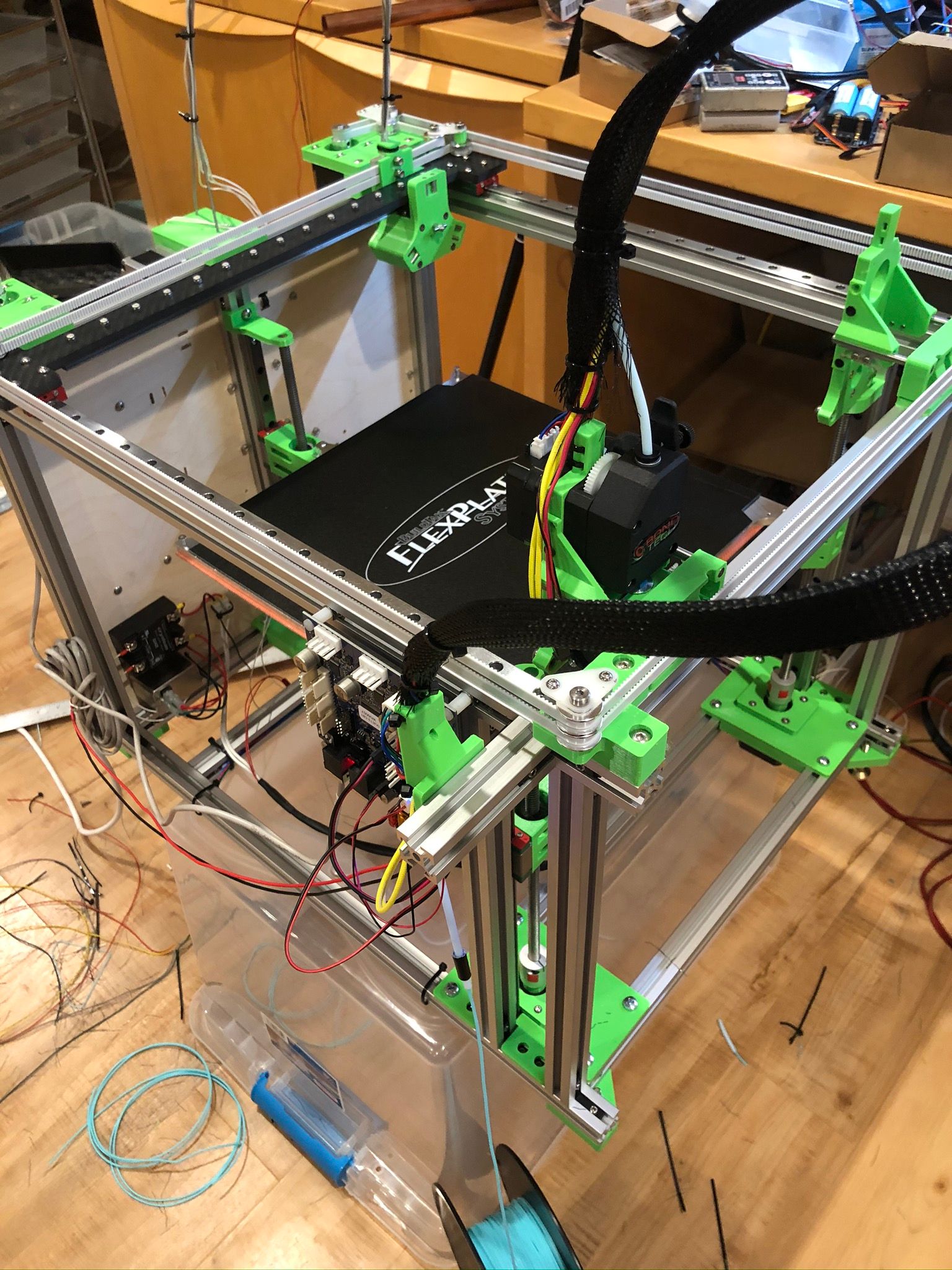
Duet 3 6HC + Expanders in multi tool printer.
-
I've chosen to use the six drivers that are on the Duet 3 6HC base board for X, Y, U (the lock/unlock for tools) and the three Z motors on the bed (which allows it to be 'self leveling' via standard functionality built in to Duet/RepRap firmware). All endstops, the bed heater, etc, are also wired to the base board.
In turn, that means the four tools are attached to expander boards. This includes motor drive, heater, fans, thermistor, etc, etc. All the wires that normally lead to a hot end.
In turn, this means the four tools can be migrated from expander boards to tool boards at some point in the future (can't do it now, as the tool boards just aren't available yet, not even beta).
-
And just a quick thought on "the four tools". Initially I do plan to build "FDM Print" tools. That is "hot ends". Jubilee has STLs that make it easy to have Bondtech extruders direct drive to E3D hot ends. And that's what I will build for the first four.
In the long run, this is a modular platform. One tool may be a Laser; another a pen (plotter). This will affect what is really needed in terms of motor driver, inputs, outputs, etc. A careful look at the picture above will show two "hot end" and two "pen plotter" tools.
This is a great reason to go to tool boards...
-
There was a 13 tool printer at ERRF that had an auto-loading brass insert tool prototype -- very nice idea IMO.
Jubilee is on my short list of "whenever I will build a tool changer" printers... Keep us posted!
-
Status update:
I've now fully wired tool 0, and extruder, to a Duet 3 expansion board. There was a small learning curve in naming conventions for RepRap 3. These were changed mostly to divorce fans/heaters/sensors into a new scheme that doesn't require a "virtual" (fake) heater to have a temperature sensor.
Anyway, once I grasped the "board.port" naming, it was pretty simple to set up. And mostly "just works".
The word "mostly" is from a few rough edges: Fans work but don't show up in Web, small things like that. All reported in separate threads.
Here is an example of the configuration of temp/heaters/fans on main and expansion. Bed heater is 0, and on main board. Everything else is on expansion 1. You can see things like "0.temp0" and "1.temp0" for the zeroth-connector on the main and expansion board, respectively. Very straightforward once you see some examples.
; Temperature sensors M308 S0 P"0.temp0" Y"thermistor" T100000 B3950 A"Bed" M308 S1 P"1.temp0" Y"thermistor" T100000 B3950 A"Ex0" M308 S2 P"1.temp1" Y"thermistor" T100000 B3950 A"Ex1" ; Heaters M950 H0 C"0.out0" T0 ; Bed. H = Heater 0, C is output for heater itself, T = Temperature sensor (defined above) M950 H1 C"1.out0" T1 ; Heater for extruder out tool 0 M950 H2 C"1.out1" T2 ; Heater for extruder out tool 1 ; Fans for hot end cooling M950 F10 C"1.out6" M106 P10 S255 H1 T45 ; S = Speed of fan Px, Hxx = heater for thermo mode, T = temps for thermo mode. M950 F11 C"1.out7" M106 P11 S255 H2 T45 ; S = Speed of fan Px, Hxx = heater for thermo mode, T = temps for thermo mode. ; Fans for print cooling M950 F0 C"1.out3" M950 F1 C"1.out4" -
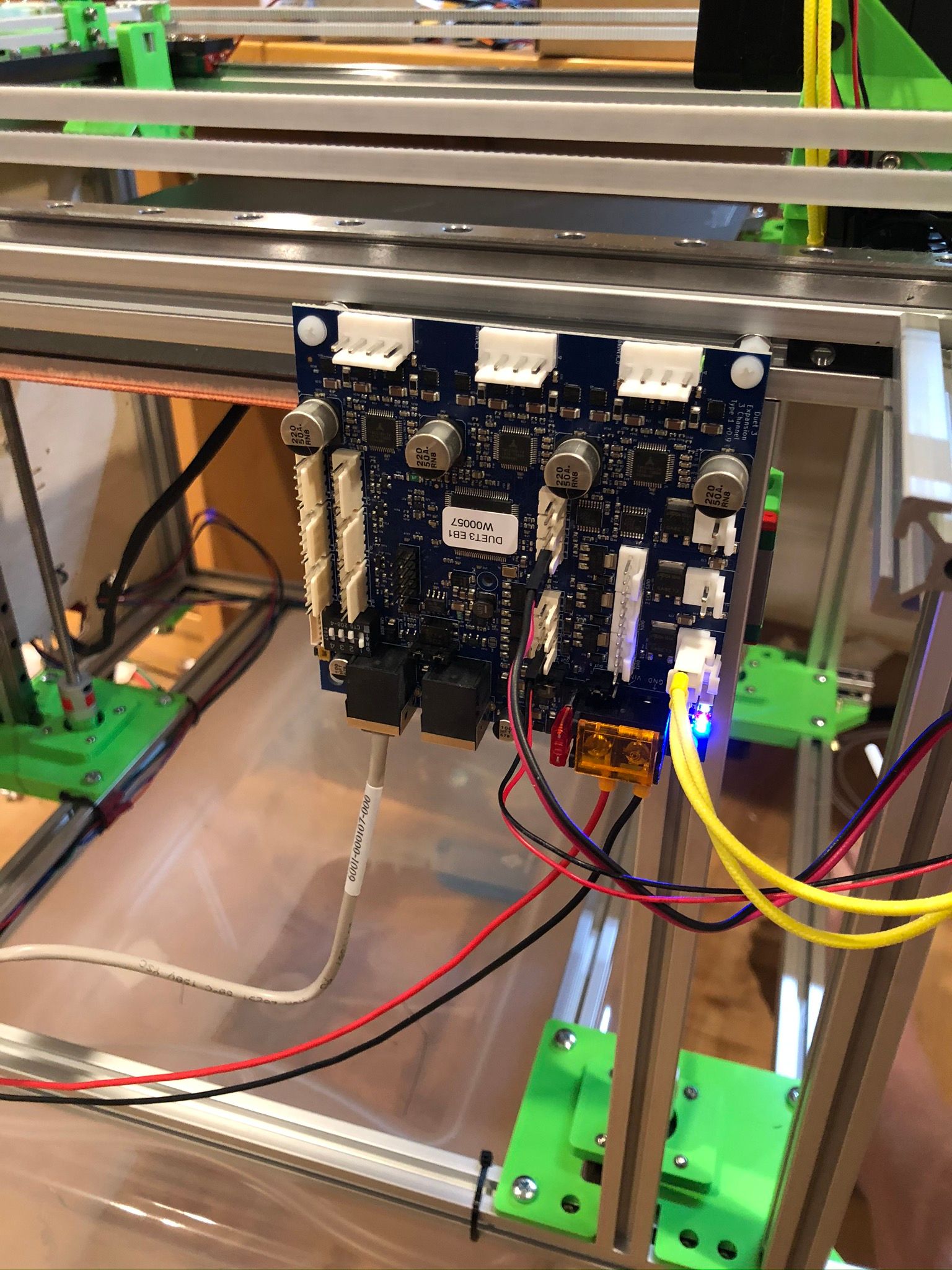
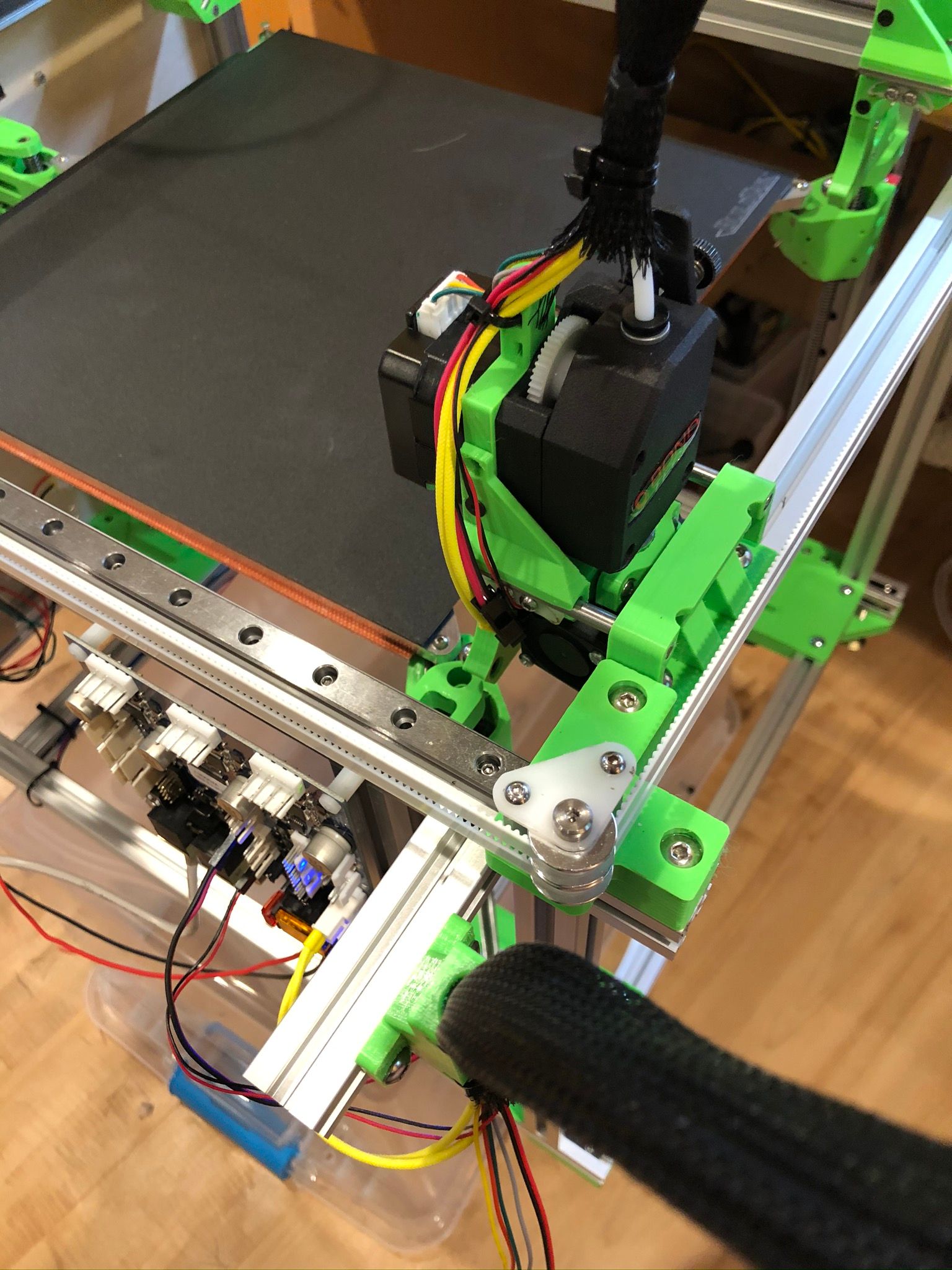
A temporary mounting point for the expansion board while I decide where to permanently mount it. Thats why the CAN and Power wires are just sort of dangling.
One pic shows the board better; the other the board plus the tool (which is parked).
-
Oh, and I just noticed I had yet to hook up the motor and one of the fans in these pics. They are all hooked up now.
-
@Danal said in Duet 3 6HC + Expanders in multi tool printer.:
There was a small learning curve in naming conventions for RepRap 3. These were changed mostly to divorce fans/heaters/sensors into a new scheme that doesn't require a "virtual" (fake) heater to have a temperature sensor.
It was also to support heaters and more particularly fans controlled by sensors not on the same board as the heater or fan.
-
@Danal Are you anticipating any degradation of the printed parts connecting the bed to the leadscrew and linear rail?
From what I've seen of the design of the Jubilee bed platform it seems like there would be heat directly transferred from the bed, through the metal balls, to the dowel pins, and to the printed part. If they are made of PLA and you raise the bed to temperatures suitable for ABS or PETG I would think that deformation would start to occur.
That's just what my initial thoughts were though, in practice it might not be even noticeable.
-
@Red-Sand-Robot Interesting point, and the "proof is in the pudding" so to speak. I will keep an eye on it.
Having said that, I'm thinking that common bed temperatures, 80, 90, things like that, are extremely unlikely to be a problem along that heat path. No math or engineering behind that thought, just gut feel.
If the printer were to end up in a heated enclosure, I'd print the parts out of something, perhaps Polycarbonate, that is better than PLA.
-
@Danal I only bring that up because on my custom Prusa style machine, my Y carriage plate is aluminum and does get noticeably hot when printing around 80-90, and since the heat transfer through air is basically non existent it must therefore be transferring from the screws attaching the heated bed to the Y carriage.
When I saw that the heated bed was placed directly on top of a PLA part that was my first concern. An easy fix would definitely be reprinting in polycarbonate, ABS/ASA, or maybe even SLS printed from nylon.
-
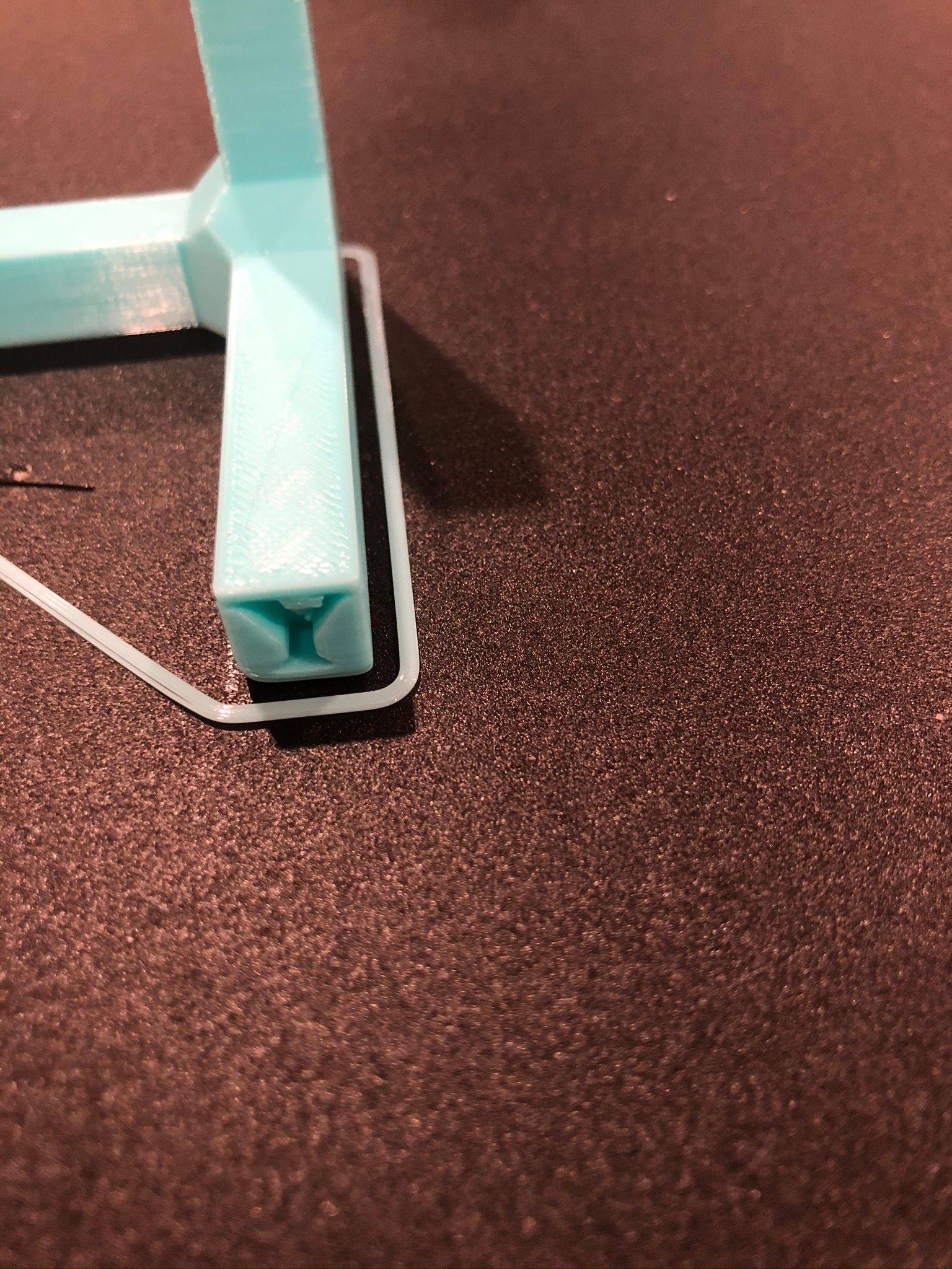
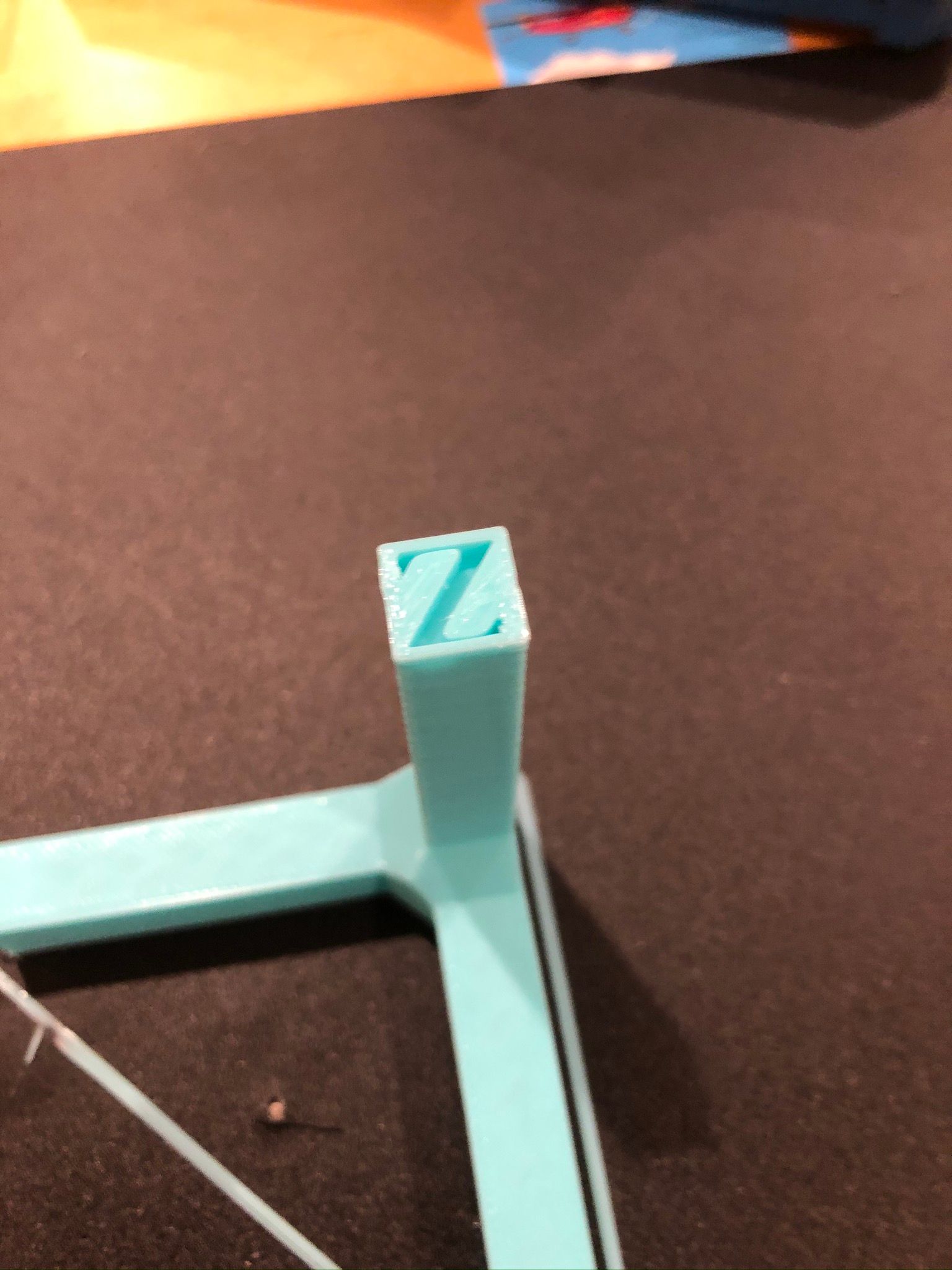
First prints. Single tool. The bed is still not really coupled into its kinematic coupling properly. Still, pretty good results.
Experimenting with mounting expansion boards on the sides. CAN bus is a huge enabler for this. Forgive the dangling wires; I will clean them up if this turns out to be a good place for the expander.
Movement and toolchange steppers on base board, limit switches on base, bed heater and temp on base; all fans, heaters, extruder motors, etc, etc, for the tool are on expansion board 1. Board 1 will soon get the second tool.
-
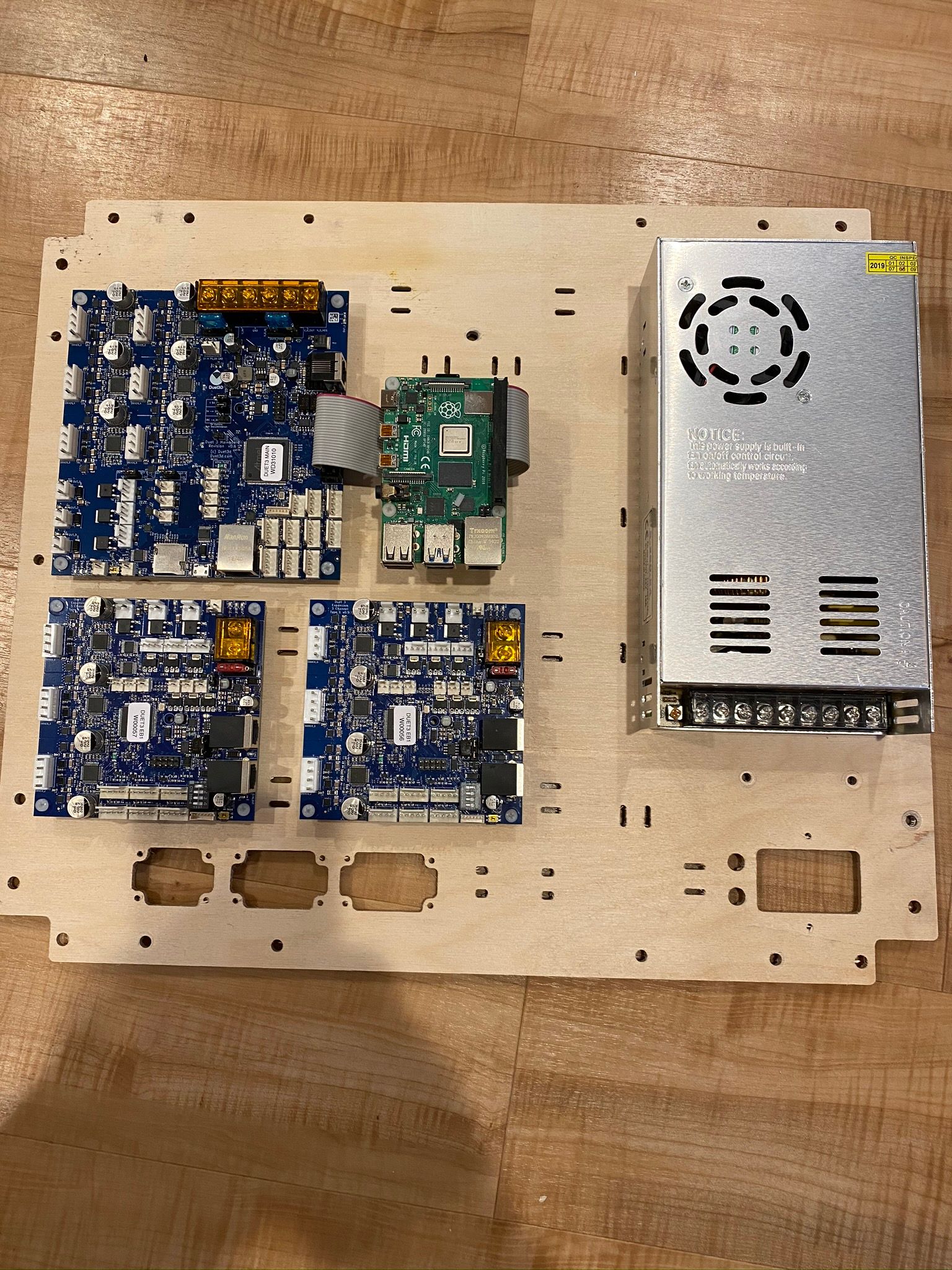
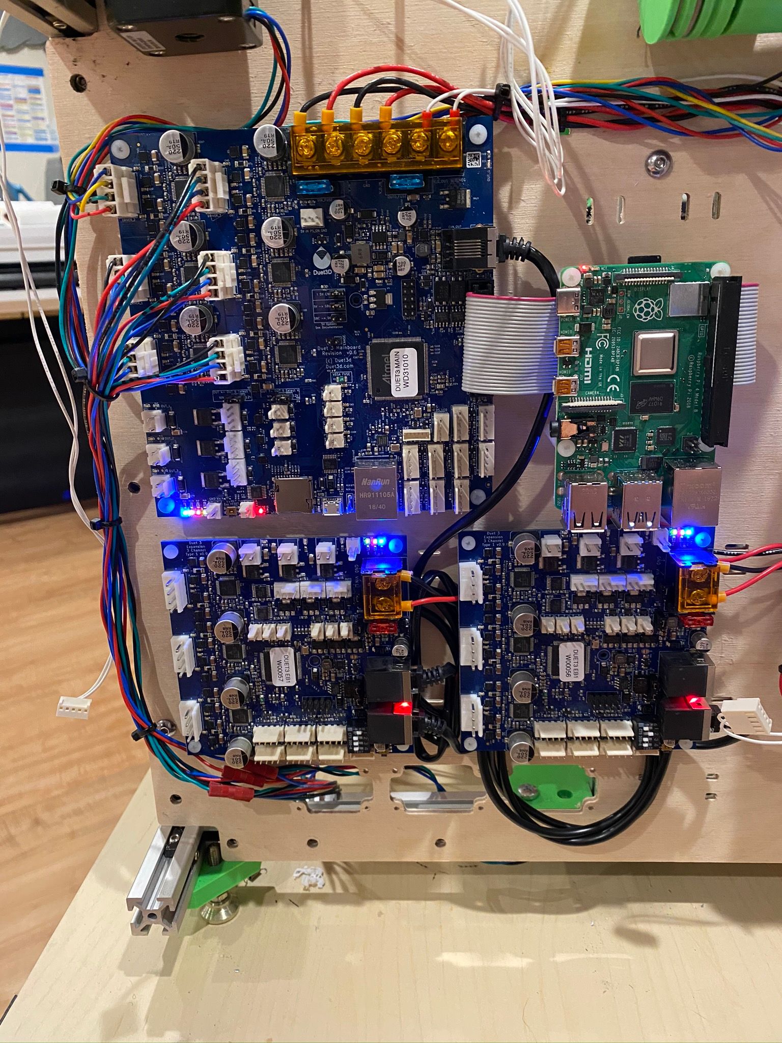
I ran with the expansion board on the side for quite some time... and... it is finally time to put the boards where they belong, and re-wire the tools. This will help the multiple tools wiring bundles not drag each other around.
Overall layout.
Mounted on the back of the printer. Main board is wired, expansions not yet.
-
thanks for sharing!
I like this project and I guess this could be my next project too! -
Thanks for sharing! How may tools do you intend to use eventually?
-
@dc42 said in Duet 3 6HC + Expanders in multi tool printer.:
Thanks for sharing! How may tools do you intend to use eventually?
Four will fit nicely in this chassis. Since the 6HC is fully occupied with no tools, I'm putting two tools on each expansion, just for symmetry.
At some point, I may rebuild and go a touch larger. With the base and two expansions, six tools would make a lot of sense.
-
I'm planning on 6 tools on my build once I get round to ordering a second 3HC
-
@jay_s_uk said in Duet 3 6HC + Expanders in multi tool printer.:
I'm planning on 6 tools on my build once I get round to ordering a second 3HC
Don't forget that we have tool boards in the pipeline, which will be available to order very soon! Perfect for Hemera direct drive extruders.
-
@dc42 said in Duet 3 6HC + Expanders in multi tool printer.:
Don't forget that we have tool boards in the pipeline, which will be available to order very soon! Perfect for Hemera direct drive extruders.
I haven't forgotten. I was very impressed by them at TCT when I saw them.
My long term goal is all Hemeras with toolboards but that will take time