@Phaedrux Hi Thanks for all of the replies. My printer has a print area of 500X500 mm. My prints are OK at the center and test prints are OK. When I print at the extremities is where I am having problems with first layer heights. My bed is well within +/- 0.5 mm level.
When I probe using G30 S-1 at the center I get a z return height of 2.4 mm which is what is entered into the config.g code. When I probe at the extremities is where I get different Z probe heights. The probe heights are identical with mesh bed leveling on or off.
Posts made by Willo47
-
RE: Mesh bed compensationposted in Tuning and tweaking
-
Mesh bed compensationposted in Tuning and tweaking
Hi , I have built a coreXY printer running a duet3d board with reprapfirmware.
I am having a problem with getting mesh bed compensation working.
I disable meshbed compensation with M561 and obtain Z probe height over various points on the bed then I activate meshbed compensation and the Z probe offsets remain identical to the disabled compensation. Has anyone been successful at getting meshbed compensaiton working. If so would you be able to share your setup code.
Thanks -
RE: Mesh bed compensationposted in Tuning and tweaking
@bernardomattiucci
I too have problem with meshbed compensation not working despite trying every conceivable code.
My firmware did not come with a mesh.g file. Can anyone tell me what it consisted of -
RE: Managing Spam accountsposted in General Discussion
@T3P3Tony Hi I am a new user and have registered account. I tried to post a new topic and it went to spam. How do I proceed to letting me post to the forum.
-
RE: Filament out sensor G code M591 queryposted in Filament Monitor
Hello dc42, thanks for the reply.
How simple was that. In carefully reading the M591 code explanation I now see right at the beginning that a pause is activated on filament sense. I put in the S1 and it worked.
Could someone remove the M581 code references please to prevent others from wasting time trying to make it work.
Thanks again for the help. -
Filament out sensor G code M591 queryposted in Filament Monitor
Hi, in the last year I have built my own Core XY printer using a Duet wifi controller with a Panel duo display and it has been working OK for some time. I am now doing larger prints and am trying to fit a filament out sensor using a simple micro switch. I have been unable to make this work.
I have been using M581 T2 E0 S0 C1 to configure the switch to trigger a sys/trigger2.g macro to pause the machine.
I used the M582 T2 to poll the switch.
When I look at the machine state on my computer interface the switch show E0 on /off when the swich is operated.I looked through previous posts and see from the administrator in Jan2019 that M581/582 should no longer be used and M591 should be used instead. Is that the case? if so perhaps some comment in the Gcode dictionary would be useful.
In my case using M591 the gcode for setup is
M591 D0 P2 C3
when I send
M591 D0 the status of my switch is correctly displayed on my computer interface.
I understood the concept of polling an interrupt in real time as I assumed the M582 command should have done but would someone explain where I should put the M582 D0 command so that it will poll the printer in real time and when the sensor changes state it how it will issue a Pause command.
I would appreciate some assistance with this as I have now spent some hours trying to figure out how to make it work without any success. -
RE: massive overextrusion, E-Steps are calibratedposted in Tuning and tweaking
Hi,
This may be a bit late to help but I will post it anyway.
I have had massive overextrusion myself and have decided the easiest way of overcoming this after much searching for the problem is to just reduce the extrusion factor until it prints well and leave it at that.I have built a large (500X500X500) core XY printer which I use for engineering components using mainly Nylon CF. This is the printer I have massive over extrusion.
I also have a Prusa MK3S and use the Prusa Slcr to do my slicing.The coreXY printer uses a Duet Wifi board with two independant Z axis drives. All of the X,Y,Z axis are calibrated and also the extruder is also calibrated. When printing I also checked that my extruder nozzle was the correct diameter (o.6mm) and that the first layer print was exactly the correct level (by using a vernier caliper to test the extrusion thickness and also the first layer thickness).
I tested my extrusion using just a single first layer and a spiral vase cylinder and found the perfect print at 0.75 extrusion factor. I now slice all of my prints using this and they come out perfectly.I spent a lot of time trying to solve why the overextrusion because there seems to be almost a religious belief in the 3D printing community that if the extrusion factor is more than 5% from 1 then there is a major problem that needs to be hunted down at all costs.
I might mention that my MK3S also over extrudes but a an extrusion factor of 0.9 seems to print OK.
Hope this was helpful.
-
RE: My CoreXY 500X500X500 duet wifi controlled printerposted in My Duet controlled machine
Reply to "Strips" re bed leveling.
My build plate is fitted to a frame which is supported at each of the four corners by the lead screws.
The build plate is supported at 9 points (three at each side and one in the middle) by 4mm threaded rod screwed into the base plate (pre threaded prior to fixing magnetic build plate) and locked with a nut. The bed held off the frame by very stiff compression springs. I made my own using 1.6mm spring steel wire wound on a 5mm mandrel and about 15mm long. The springs need to be stiff enough to be able to bend the 5mm thick build plate a small amount so that any bow can be removed from the plate.
For initial leveling I printed a mount for a dial gauge on the extruder carriage and used that to get it withing +/-50 microns. This saved a lot of time as you can get almost instant indication of how level the bed is.
Once that was done I fitted the extruder and used the BLtouch probe to probe the bed using the via the DWC. Initially I only had 9 points on the mesh which coincided with the bed adjustement points. After each adjustment I did the two point be leveling prior to doing another mesh be leveling probe. It took few itterations to get it level. Once I was happy I then did a 64 point mesh bed grid which I use when doing a print. The final bed leveling is done with the bed heated to 80deg C which I use for the first layer bed temperature for PETG which I am currently printing.
I am currently printing a 400mm 5 spoke test wheel to check out the bed. Looks good so far. -
RE: My CoreXY 500X500X500 duet wifi controlled printerposted in My Duet controlled machine
First reply is re the variable belt tensioner. The system works a treat in that I have the X carriage at the Y max position where it is next to the rear frame where I can get a reference as to if the X carriage is straight. I then tune the tension until the carriage is parallel to the frame and then tighten the nuts underneath.
The picture shows the system with printed parts using PETG. Unfortunately as I use bed temperatures of up to 90deg C this is above the glass temperature of PETG and the plastic tends to give. I have just re-made these components from aluminium which has solved the problem. -
RE: My CoreXY 500X500X500 duet wifi controlled printerposted in My Duet controlled machine
The two rails for the Z axis are on the rear of the frame. I have connected one side of the bed frame via a small (100mm) horzontal rail and a rail slide to allow for thermal expansion. Two rails are sufficient to locate the bed.
-
RE: My CoreXY 500X500X500 duet wifi controlled printerposted in My Duet controlled machine
Hi there, I have reduced the size of my pictures and will uploadload them onto the site to solve any further problems.
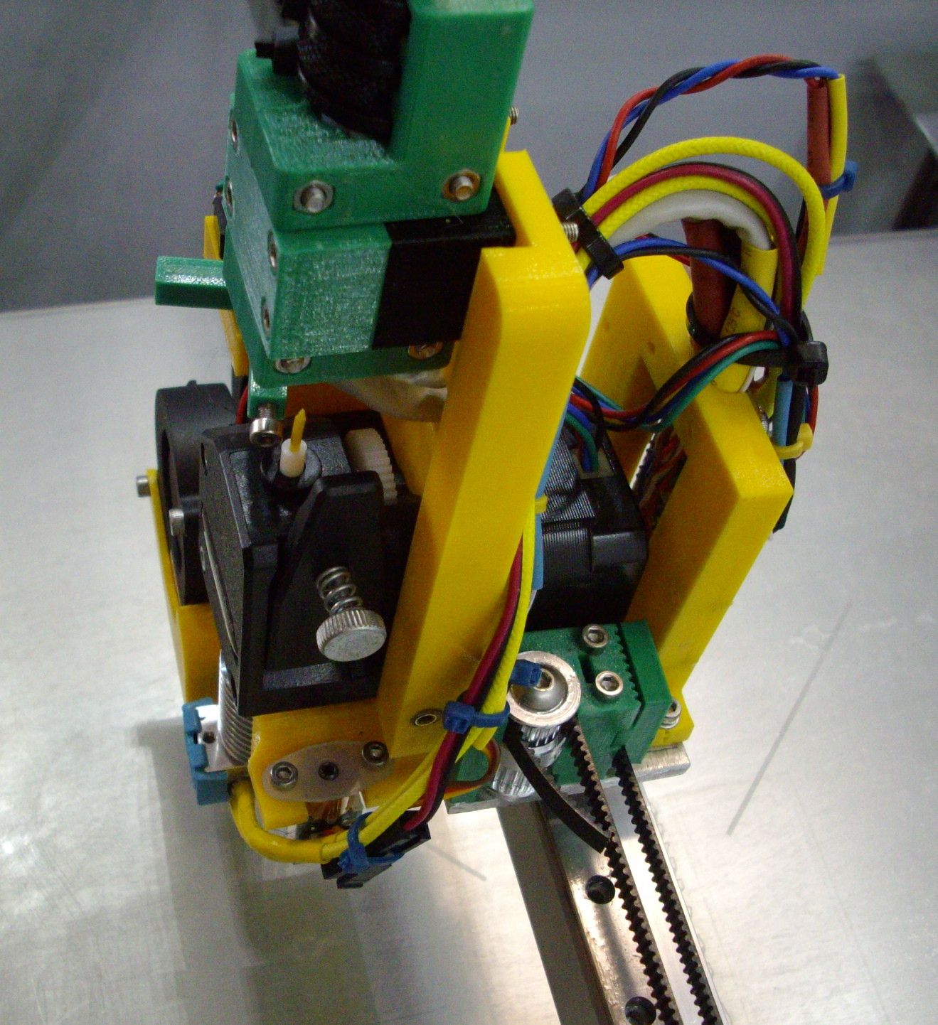 Picture of extruder with continously variable belt tensioner.
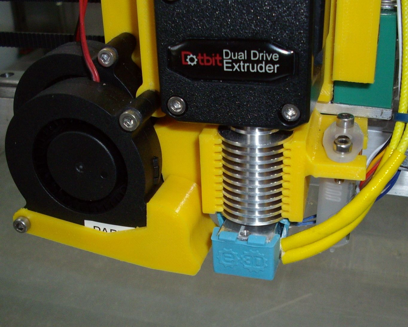
Hotend fan shroud with integrated BL touch mount.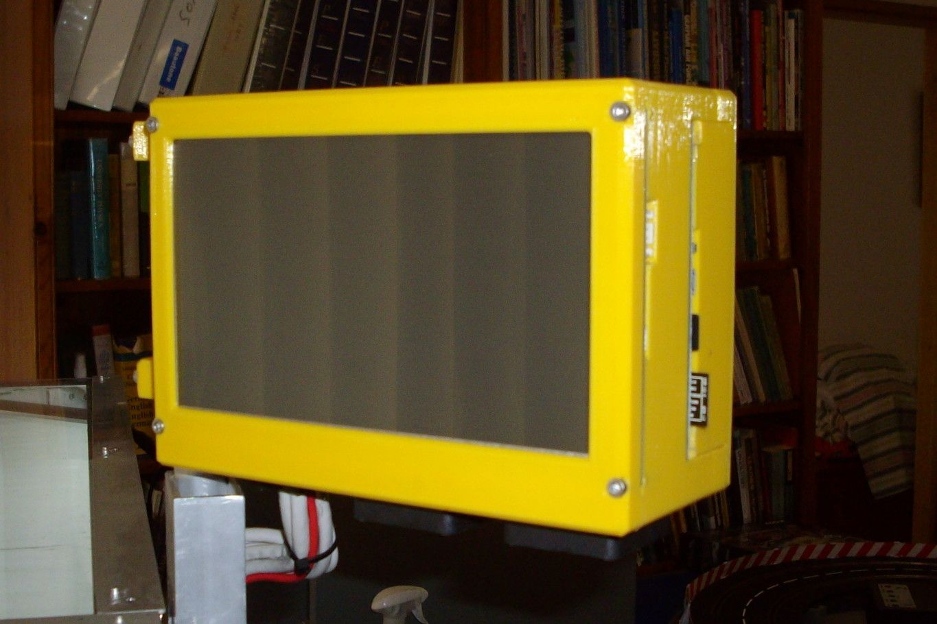
Duet wifi and 7inch panel due case on swivel mount.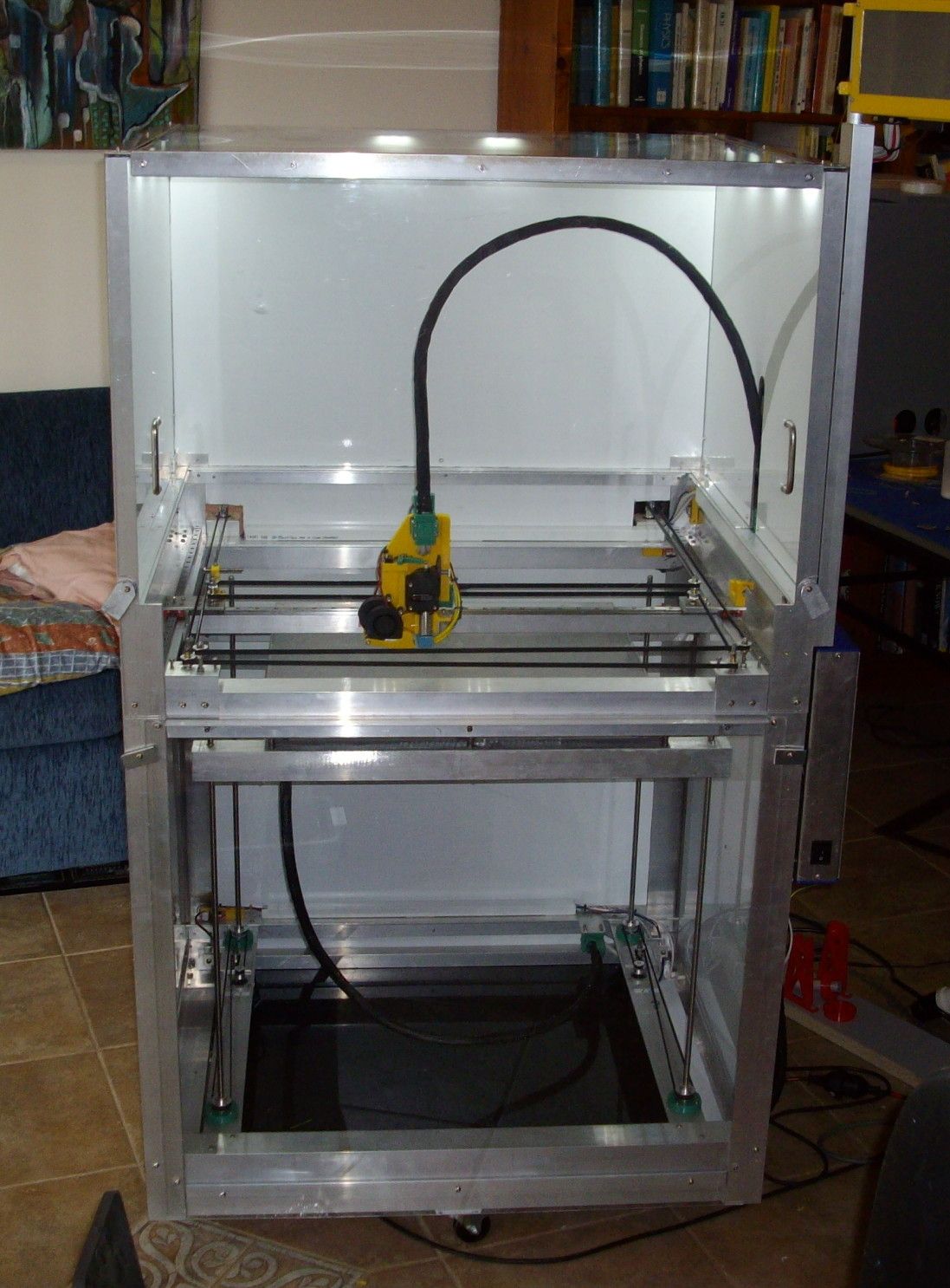
The printer fully enclosed suitable for printing nylon and ABS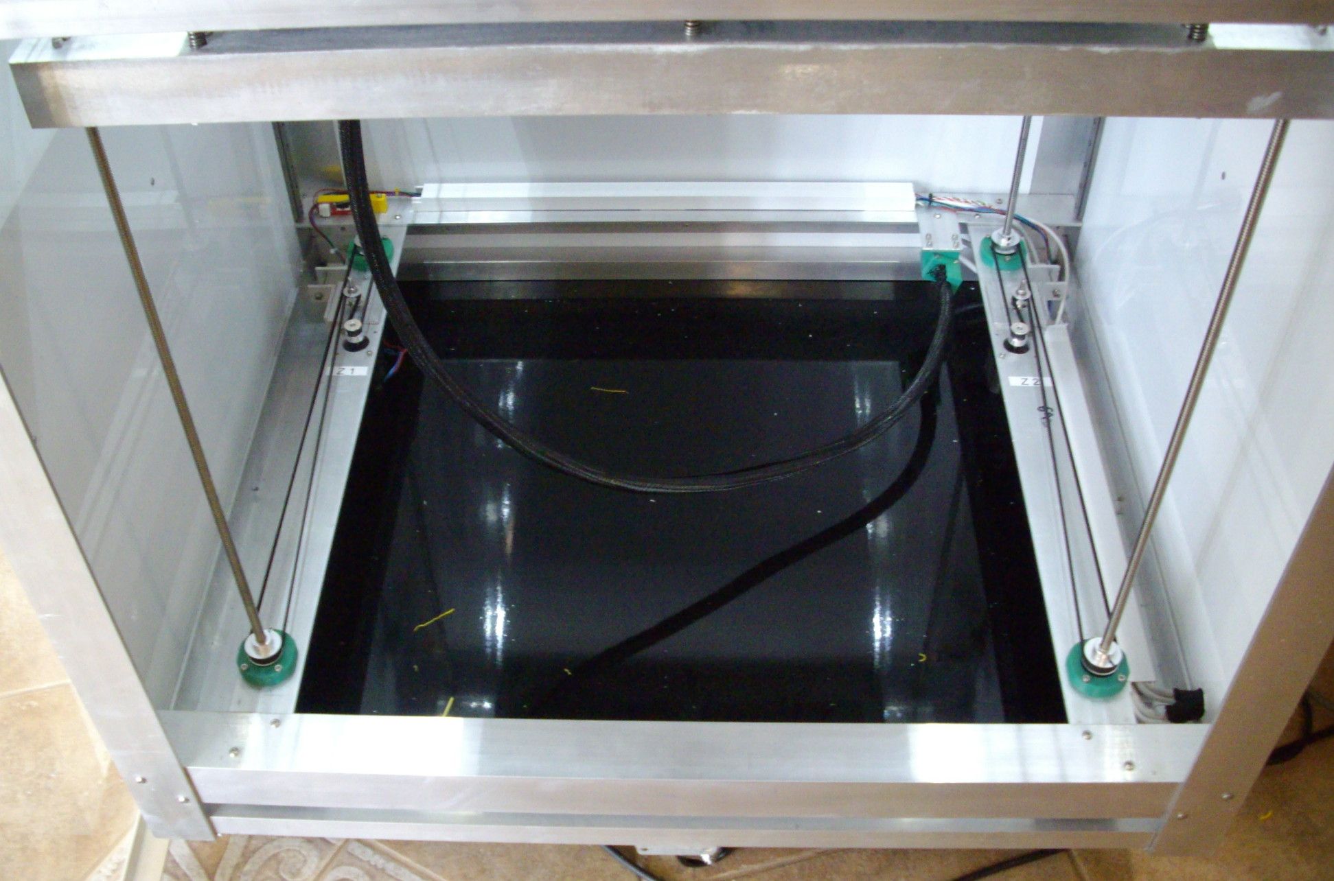
Four lead screws Z mount driven by two independent Z steppers to allow two point bed leveling.Hope this works.
-
RE: My CoreXY 500X500X500 duet wifi controlled printerposted in My Duet controlled machine
Hi,
Posting links on the forum is new to me so obviously not doing the right thing. The photos are on google photos and I just copy and pasted the links associated with the photo. Perhaps it requires some sharing to be activated. Any hints on how to get some working links would be appreciated. When I click on the link it works so difficult for me to chech as an outsider. -
My CoreXY 500X500X500 duet wifi controlled printerposted in My Duet controlled machine
Hello,
I have just got my Core XY printer to a stage where I can now start printing things. I have had a huge help from this forum by just reading about issues relevant to my stage of the printer construction. Just thought I would show some pics of how I went about my design.(https://photos.google.com/photo/AF1QipOCxdsFYbNfOynEF8DJ_eslK6yXvbeizdb9B6g_)
The printer is fully enclosed as I want to print Nylon and CF Nylon which require an enclosure. All of the electronics is therefore external. The Duet wifi and a seven inch PanelDue is in a custom box with all external connectors accessible.([https://photos.google.com/photo/AF1QipPtProFC6gnkE2F4rFxIv4g-gSa9WsLlP5HueQ7))
I started the design with a flexible PEX print surface which I purchased from Wham Bam (I have no links with this company). The build plate is 5mm aluminium sheet (chopped from big sheet by local metal merchant) and I have used a lead screw on each corner paired to be driven by two independant Z motors as I did not want to use an expansion board. There are only two rails for the Z axis and I have used a short rail to connect one end of the build surface to allow for thermal expansion.The plate is heated with 4X200 watt 240V heaters. The plate is mounted on heavy duty springs (home made) to give 9 point bed leveling . The plate has come in better than +/- 50 microns.
https://photos.google.com/photo/AF1QipOi53EVtrkPGIwPXEf1okGsadRf0iDHVKAQJR-t!
I am using a genuine E3D V6 24 V extruder to allow me to print high temperatures. Note the custom cooling shroud with integrated BLtouch mount. https://photos.google.com/photo/AF1QipOjGvtmdMIGpEwgFb4r7VSW8ZvGot_9XeFl7nXJ
I have designed a continuously adjustable tension system for the coreXY belts to allow easy setting of the belt tensions. If the belt tension is not identical the X carriage tends to rack.https://photos.google.com/photo/AF1QipOS5LQaY3V-R69XJoLthSARXXTXbVTnu6sZ3Rkx
I have connect one end of the X carriage via a rail slide to allow for thermal expansion.
The filament out sensor uses a microswitch driven by a simple arm fully adjustable. The filament runs on the head of a 3mm bolt so will not wear in a hurry.
Test prints show that the mechanics are sound. -
Solutions to Core XY printer successposted in Tuning and tweaking
Hi, I have just spent some months building a CoreXY printer from scratch using rails with a print volume of 500X500X500 mm and have just succeeded (after a huge effort) in tuning the printer and getting a good quality print.
I would like to thank all of the contributors to this forum for the information and also the RepRap community for all the work put in. Without them I would not have succeeded. I have just observed the forum and this is my first post.
I would like to put a few items of information on this post which may help others on their journey:- I had problems right at the end in getting a good first layer. I was getting a lot of stippling on the first layer. Changing temperature, layer height and extrusion widths did nothing to solve it. The problem turned out to be simple. During the tuning process I used the same print over and over and did not clean the bed after each print. I was using PETG for tests and adhesion is not generally a problem. A clean with Isopropyl alcohol solved the problem. I am using a flexible buid plate from Wham Bam using PEX.
- The live Z for tuning first layer height which is available on the Prusa Original MK3 is not available on RepRap firmware. Baby stepping implemented on the DWC does not seem to work. Here is my solution :
Using M206 does change the end stop ie M206 Z0.05 effectively moves the bed coordinates to lower the extruder head. If you want to lower further you need M206 Z0.10 and so on . I have made a series of macros to move the head up and down. I have made a simple square print to fine tune my Z height. Once OK I send a M500 to store it in EEPROM. In my print start up code I use M501 to read the value back. If you use mesh bed compensation the M206 commands seem to have no effect during the print so I do my tuning prior to printing. Once tuned the setting seems to remain OK. - Initially I used a non temperature compensated inductive Z probe which drifted too much with temperature so I replaced it with a genuine BL touch probe. Thanks again for the post by Betrue3D for the invaluable informatin. I had a few consitency problems which turned out to be not a probe problem but how I mounted the probe. The probe mount has to be closely associated with the hotend tip and to that end I printed a custom cooling shroud for the hotend with ribs which engate with the hotend heat sink and I directly printed the BLtouch mount onto the shroud. The relationship between the hotend and the probe now remain constant. I do however do all of my calibration with the hotend at temperature. I also set my trigger threshold to 500 to make sure that I don't get inconsistent triggering due to electrical noise.
- Make sure that the Z homing point is exactly the same place as one of the mesh bed leveling probe points. I had a bed crash in the middle of the bed which caused a dimple in the print bed (the homeall.G made by the configurator swapped Z with the Y axis which caused the problem). I happened to home on this dimple but did not probe on this point. The bed mesh compensation map varied considerably in height until I moved the home and probe to the same point (in the middle and away from the dimple) As a check , irrespective of how level your bed is, the home and probe point on the mesh bed should always be close to zero.
Hope the above may helps someone on their journey to 3D printing success.