@ironhydroxide Q wasn't directed at me, but i'll throw out a quick fix that could potentially be a future Duet accessory. Ditch the Duet ribbon header/cable and replace it with a FPC BOB. The big ribbon/header connector Duet uses doesn't really buy you much as spi is limited in signal distance any away. Put a FPM connectyor on the Mag board and afix the driver board 90deg to the motor body. That is if there is room on one of the sides of the motor body.
Posts made by wayneosdias
-
RE: 1HCL compatibility questionposted in General Discussion
-
RE: 1HCL compatibility questionposted in General Discussion
@dc42 yes thanks re 2240.
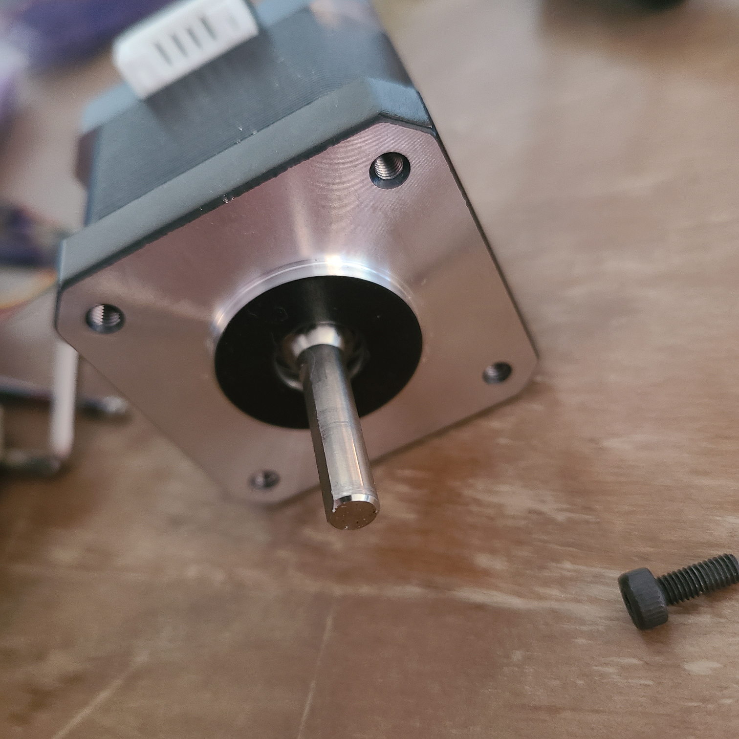
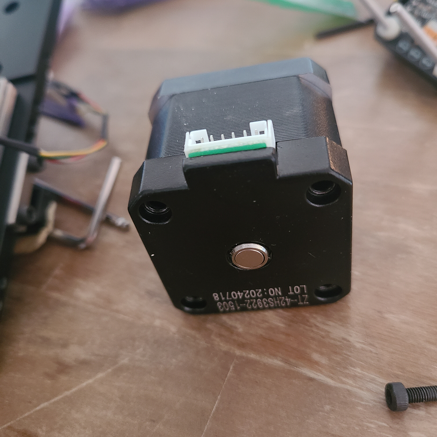
Re motor/magnets. I have purchased every flavor of the MKS 42Servo B C D and some diff/similar control boards from btt. They all kinda initially work but would become unstable at some point, overshoot/correct and or lose their 'mind' requiring an in situ recalibration. These were just the control boards mounted to the back of old nema17 motors with magnets glued to the shaft.I then tried a motor/control board combo of MKS servo D and it has worked very well in terms of long term stability. When I installed the motor, I noticed the drive side of the shaft. It appears to be an 8mm shaft turned down to 5mm. Taking the control board off looking at the non drive of the shaft and it appears to be milled with the magnet recessed into it. Or maybe the magnet is banded to the shaft? What ever may be the case, the fb/encoding of this controller/motor combo has been rocks solid.
Just food for thought
-
RE: 1HCL compatibility questionposted in General Discussion
Well it's really a testament to David, Duet and the Moderators. I wouldn't even know where to start without them. Mechatronics isn't my thing even though I rely on 4 one-off purpose-built machines for my business. I can just scheme general design concepts and leverage the Duet system to meet the control needs.
-
RE: 1HCL compatibility questionposted in General Discussion
@ironhydroxide
Hi Iron,Interesting offer, but I simply don't have the bandwidth to take on such a project or attempt to support it. With the qty you're looking at, Duet and or possibly a sub-contractor would be your best bet. That said, sounds like your design criteria would be fairly easy to meet, but one off propriety in nature. You need to get a design engineering quote, maybe the folks at Duet could point you in the right direction.
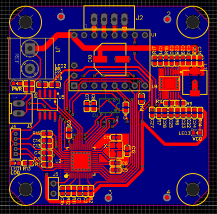
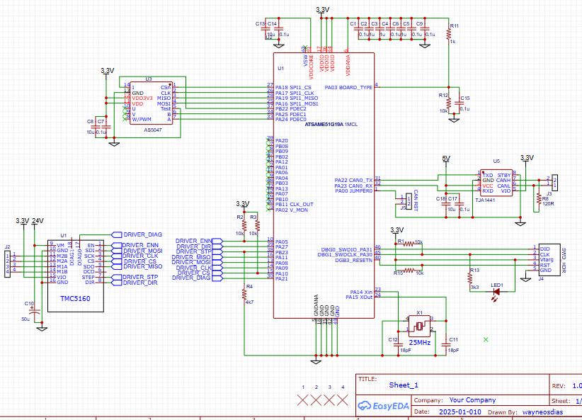
That said I'm just throwing my design out there to share w the community. I didn't put out the full schematic, heres the supply side of things, 24V 5V 3v3. Fyi the pic of the pcb i posted above was a first pass I did in a couple of hrs. Im sure its going to change after some more DRC checks. Ill prolly order the board Monday. Its simply to illustrate the Duet control accessory scheme is flexible enough to meet what it is you're proposing, even with some of your physical design constraints.
I am editing this post by removing the V supply schematic. The schematic was pulled from a different design and not fully reviewed for use in this case. Upon review the circuit needs to be reworked and not acceptable as initially posted.
-
RE: 1HCL compatibility questionposted in General Discussion
@ironhydroxide Hey Iron, This will be a Nema17 mounted Duet 1HCL + Duet Magnet board without any gpio. Im keeping all the original 1HCL Duet peripheral pin assignments, just not using all of them to speed up the process.
This will be my 2nd Custom Duet Expansion. The First go around I added accelerometer, 2 addl drivers and messed around w the pin assignments. It all works great but took a couple weeks to get right. I think the above should work as intended much quicker by not going off script with pin/peripheral assignments. I just don't have time to keep the machine down, I use it for production.
I always order a couple boards. Once I get one built and confirm fxn I can send you a spare pcb if your in the states. In keeping w Duet opensource Ill make all dev files available if you feel like using the design on some level. Keep in mind some of my apparently odd part choices are based on what I have on hand, like the full reel of dual channel Vregs my company is not going to use...
-
RE: 1HCL compatibility questionposted in General Discussion
@ironhydroxide @dc42
I just did this. Just for my pnp set up to get ride of the MKS Servo42D. Basically 1HCL + mag board wo any io
-
RE: Custom 1HCL HW/FW bootloader issuesposted in Firmware developers
@dc42
Just to put a bow on this (Merry Xmas") ). I got it all working. It took another board rev as I had a couple hw hiccups. This included to swapping the MAX3051 to the TJA1441A CAN xcvr per David's #2 note. Any rate, brand new mcu flashed the bootloader first go. I had to first set the fuses as I listed above. The default fuses had several differences, but I didn't note them.
). I got it all working. It took another board rev as I had a couple hw hiccups. This included to swapping the MAX3051 to the TJA1441A CAN xcvr per David's #2 note. Any rate, brand new mcu flashed the bootloader first go. I had to first set the fuses as I listed above. The default fuses had several differences, but I didn't note them.Also, all gpio, motor drivers and accelerometer are working as intended. interested. The '1HCL' is config'd as;
x3 step/dir drives
x2 med current outputs
x4 inputs, 24v tol
x1 lis3dH. I have the W on hand but just wanted to get the original circuit working first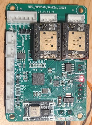
I attached the final config with all the extraneous comments deleted in case anyone is interested.
/* * EXP1HCLv1_0.h * * Created on: 3 Dec 2021 * Author: David */ #ifndef SRC_CONFIG_EXP1HCLV1_0_H_ #define SRC_CONFIG_EXP1HCLV1_0_H_ #include <Hardware/PinDescription.h> #define BOARD_TYPE_NAME "EXP1HCL" #define BOOTLOADER_NAME "SAME5x" // General features #define HAS_VREF_MONITOR 0 #define HAS_VOLTAGE_MONITOR 0 #define HAS_12V_MONITOR 0 #define HAS_CPU_TEMP_SENSOR 1 #define HAS_ADDRESS_SWITCHES 0 #define HAS_BUTTONS 1 // Drivers configuration #define SUPPORT_DRIVERS 1 #define HAS_SMART_DRIVERS 0 #define HAS_STALL_DETECT 0 #define SINGLE_DRIVER 0 #define SUPPORT_SLOW_DRIVERS 0 #define SUPPORT_DELTA_MOVEMENT 0 #define DEDICATED_STEP_TIMER 1 #define ACTIVE_HIGH_STEP 1 // 1 = active high, 0 = active low #define ACTIVE_HIGH_DIR 1 // 1 = active high, 0 = active low #define ACTIVE_HIGH_ENABLE 1 #define SUPPORT_TMC51xx 0 #define SUPPORT_TMC2160 0 #define SUPPORT_TMC2660 0 #define SUPPORT_TMC22xx 0 #define SUPPORT_CLOSED_LOOP 0 #define SUPPORT_BRAKE_PWM 0 constexpr size_t NumDrivers = 3; constexpr size_t MaxSmartDrivers = 0; PortGroup * const StepPio = &(PORT->Group[1]); // the PIO that all the step pins are on (port B) constexpr Pin StepPins[NumDrivers] = { PortBPin(8), PortBPin(22), PortBPin(23) }; constexpr Pin DirectionPins[NumDrivers] = { PortBPin(9), PortAPin(24), PortAPin(27) }; constexpr Pin EnablePins[NumDrivers] = { PortBPin(2), PortAPin(20), PortAPin(25) }; #define SUPPORT_THERMISTORS 0 #define SUPPORT_SPI_SENSORS 1 #define SUPPORT_DMA_NEOPIXEL 0 #ifdef DEBUG # define SUPPORT_I2C_SENSORS 0 // in debug mode the SERCOM is used for debugging # define SUPPORT_LIS3DH 0 #else # define SUPPORT_I2C_SENSORS 0 # define SUPPORT_LIS3DH 1 #endif #define SUPPORT_DHT_SENSOR 0 #define NUM_SERIAL_PORTS 0 #define USE_MPU 0 #define USE_CACHE 1 constexpr bool UseAlternateCanPins = true; constexpr size_t MaxPortsPerHeater = 0; constexpr size_t NumThermistorInputs = 0; constexpr Pin BoardTypePin = PortAPin(3); // Diagnostic LEDs constexpr Pin LedPins[] = { PortAPin(31), PortAPin(30) }; constexpr bool LedActiveHigh = false; constexpr Pin VinMonitorPin = PortAPin(2); //constexpr Pin V12MonitorPin = PortAPin(6); //constexpr float VinDividerRatio = (100.0 + 5.1)/5.1; //constexpr float V12DividerRatio = (60.4 + 4.7)/4.7; //constexpr float VinMonitorVoltageRange = VinDividerRatio * 3.3; //constexpr float V12MonitorVoltageRange = V12DividerRatio * 3.3; constexpr Pin ButtonPins[] = { PortAPin(0) }; //Used for CAN ID reset #if SUPPORT_I2C_SENSORS // I2C using pins PA12,13 constexpr uint8_t I2CSercomNumber = 2; constexpr Pin I2CSDAPin = PortAPin(12); constexpr GpioPinFunction I2CSDAPinPeriphMode = GpioPinFunction::C; constexpr Pin I2CSCLPin = PortAPin(13); constexpr GpioPinFunction I2CSCLPinPeriphMode = GpioPinFunction::C; # define I2C_HANDLER0 SERCOM2_0_Handler # define I2C_HANDLER1 SERCOM2_1_Handler # define I2C_HANDLER2 SERCOM2_2_Handler # define I2C_HANDLER3 SERCOM2_3_Handler #endif #if SUPPORT_LIS3DH # if SUPPORT_I2C_SENSORS # define ACCELEROMETER_USES_SPI (0) // accelerometer is connected via I2C constexpr Pin Lis3dhInt1Pin = PortAPin(20); // same as io1.in # else # define ACCELEROMETER_USES_SPI (1) // accelerometer is connected via SPI constexpr Pin Lis3dhCsPin = PortAPin(18); // same as encoder CS pin constexpr Pin Lis3dhInt1Pin = PortAPin(12); // same as io1.in # endif #endif // Shared SPI (used for interface to encoders, not for temperature sensors) constexpr uint8_t SspiSercomNumber = 1; constexpr uint32_t SspiDataInPad = 3; constexpr Pin SSPIMosiPin = PortAPin(16); constexpr GpioPinFunction SSPIMosiPinPeriphMode = GpioPinFunction::C; constexpr Pin SSPISclkPin = PortAPin(17); constexpr GpioPinFunction SSPISclkPinPeriphMode = GpioPinFunction::C; constexpr Pin SSPIMisoPin = PortAPin(19); constexpr GpioPinFunction SSPIMisoPinPeriphMode = GpioPinFunction::C; // Clock generator pin for TMC2160 constexpr uint8_t ClockGenGclkNumber = 5; constexpr Pin ClockGenPin = PortBPin(11); constexpr GpioPinFunction ClockGenPinPeriphMode = GpioPinFunction::M; // Table of pin functions that we are allowed to use constexpr PinDescription PinTable[] = { // TC TCC ADC SERCOM in SERCOM out Exint PinName // Port A { TcOutput::none, TccOutput::none, AdcInput::none, SercomIo::none, SercomIo::none, 0, nullptr }, // PA00 ButtonPins[0] PortAPin(0) CANRST { TcOutput::tc2_1, TccOutput::none, AdcInput::none, SercomIo::none, SercomIo::none, Nx, nullptr }, // PA01 { TcOutput::none, TccOutput::none, AdcInput::adc0_0, SercomIo::none, SercomIo::none, Nx, "ate.vin" }, // PA02 VinMonitorPin PortAPin(2) { TcOutput::none, TccOutput::none, AdcInput::adc0_1, SercomIo::none, SercomIo::none, Nx, nullptr }, // PA03 BoardTypePin PortAPin(3) { TcOutput::none, TccOutput::none, AdcInput::adc0_4, SercomIo::none, SercomIo::none, Nx, "out1" }, // PA04 { TcOutput::none, TccOutput::none, AdcInput::none, SercomIo::none, SercomIo::none, Nx, "out0" }, // PA05 { TcOutput::none, TccOutput::none, AdcInput::adc0_6, SercomIo::none, SercomIo::none, 6, "io0.in" }, // PA06 { TcOutput::none, TccOutput::none, AdcInput::none, SercomIo::none, SercomIo::none, Nx, nullptr }, // PA07 { TcOutput::none, TccOutput::none, AdcInput::none, SercomIo::none, SercomIo::none, Nx, nullptr }, // PA08//nullptr { TcOutput::none, TccOutput::none, AdcInput::none, SercomIo::none, SercomIo::none, 9, "io1.in" }, // PA09 { TcOutput::none, TccOutput::none, AdcInput::none, SercomIo::none, SercomIo::none, 10, "io2.in" }, // PA10 { TcOutput::none, TccOutput::none, AdcInput::none, SercomIo::none, SercomIo::none, 11, "io3.in" }, // PA11 { TcOutput::none, TccOutput::tcc1_2F, AdcInput::none, SercomIo::none, SercomIo::none, 12, nullptr }, // PA12 Lis3dhInt1Pin = PortAPin(12); { TcOutput::none, TccOutput::none, AdcInput::none, SercomIo::none, SercomIo::none, Nx, nullptr }, // PA13 No IO!! { TcOutput::none, TccOutput::none, AdcInput::none, SercomIo::none, SercomIo::none, Nx, nullptr }, // PA14 crystal { TcOutput::none, TccOutput::none, AdcInput::none, SercomIo::none, SercomIo::none, Nx, nullptr }, // PA15 crystal { TcOutput::none, TccOutput::none, AdcInput::none, SercomIo::none, SercomIo::none, Nx, nullptr }, // PA16 SSPIMosiPin = PortAPin(16); { TcOutput::none, TccOutput::none, AdcInput::none, SercomIo::none, SercomIo::none, Nx, nullptr }, // PA17 SSPISclkPin = PortAPin(17); { TcOutput::none, TccOutput::none, AdcInput::none, SercomIo::none, SercomIo::none, 2, "spi.cs0" }, // PA18 Lis3dhCsPin = PortAPin(18); { TcOutput::none, TccOutput::none, AdcInput::none, SercomIo::none, SercomIo::none, Nx, nullptr }, // PA19 SSPIMisoPin = PortAPin(19); { TcOutput::none, TccOutput::none, AdcInput::none, SercomIo::none, SercomIo::none, Nx, nullptr }, // PA20 { TcOutput::none, TccOutput::none, AdcInput::none, SercomIo::none, SercomIo::none, Nx, nullptr }, // PA21 { TcOutput::none, TccOutput::none, AdcInput::none, SercomIo::none, SercomIo::none, Nx, nullptr }, // PA22 CAN0 Tx { TcOutput::none, TccOutput::none, AdcInput::none, SercomIo::none, SercomIo::none, Nx, nullptr }, // PA23 CAN0 Rx { TcOutput::none, TccOutput::none, AdcInput::none, SercomIo::none, SercomIo::none, Nx, nullptr }, // PA24 { TcOutput::none, TccOutput::none, AdcInput::none, SercomIo::none, SercomIo::none, Nx, nullptr }, // PA25 { TcOutput::none, TccOutput::none, AdcInput::none, SercomIo::none, SercomIo::none, Nx, nullptr }, // PA26 not on chip { TcOutput::none, TccOutput::none, AdcInput::none, SercomIo::none, SercomIo::none, Nx, nullptr }, // PA27 { TcOutput::none, TccOutput::none, AdcInput::none, SercomIo::none, SercomIo::none, Nx, nullptr }, // PA28 not on chip { TcOutput::none, TccOutput::none, AdcInput::none, SercomIo::none, SercomIo::none, Nx, nullptr }, // PA29 not on chip { TcOutput::none, TccOutput::none, AdcInput::none, SercomIo::none, SercomIo::none, Nx, nullptr }, // PA30 LedPins[1] PortAPin(30) { TcOutput::none, TccOutput::none, AdcInput::none, SercomIo::none, SercomIo::none, Nx, nullptr }, // PA31 LedPins[0] PortAPin(31) // Port B { TcOutput::none, TccOutput::none, AdcInput::none, SercomIo::none, SercomIo::none, Nx, nullptr }, // PB00 not on chip { TcOutput::none, TccOutput::none, AdcInput::none, SercomIo::none, SercomIo::none, Nx, nullptr }, // PB01 not on chip { TcOutput::none, TccOutput::tcc2_2F, AdcInput::none, SercomIo::none, SercomIo::sercom5d, Nx, nullptr }, // PB02 EnablePins[2] PortBPin(2) { TcOutput::none, TccOutput::none, AdcInput::adc0_15, SercomIo::sercom5d, SercomIo::none, Nx, nullptr }, // PB03 { TcOutput::none, TccOutput::none, AdcInput::none, SercomIo::none, SercomIo::none, Nx, nullptr }, // PB04 not on chip { TcOutput::none, TccOutput::none, AdcInput::none, SercomIo::none, SercomIo::none, Nx, nullptr }, // PB05 not on chip { TcOutput::none, TccOutput::none, AdcInput::none, SercomIo::none, SercomIo::none, Nx, nullptr }, // PB06 not on chip { TcOutput::none, TccOutput::none, AdcInput::none, SercomIo::none, SercomIo::none, Nx, nullptr }, // PB07 not on chip { TcOutput::none, TccOutput::none, AdcInput::adc0_2, SercomIo::none, SercomIo::none, Nx, nullptr }, // PB08 StepPins[2] PortBPin(8) { TcOutput::none, TccOutput::none, AdcInput::adc0_3, SercomIo::none, SercomIo::none, Nx, nullptr }, // PB09 DirectionPins[2] PortBPin(9) { TcOutput::none, TccOutput::tcc0_4F, AdcInput::none, SercomIo::none, SercomIo::none, Nx, nullptr }, // PB10 { TcOutput::none, TccOutput::none, AdcInput::none, SercomIo::none, SercomIo::none, Nx, nullptr }, // PB11 ClockGenPin PortBPin(11); { TcOutput::none, TccOutput::none, AdcInput::none, SercomIo::none, SercomIo::none, Nx, nullptr }, // PB12 not on chip { TcOutput::none, TccOutput::none, AdcInput::none, SercomIo::none, SercomIo::none, Nx, nullptr }, // PB13 not on chip { TcOutput::none, TccOutput::none, AdcInput::none, SercomIo::none, SercomIo::none, Nx, nullptr }, // PB14 not on chip { TcOutput::none, TccOutput::none, AdcInput::none, SercomIo::none, SercomIo::none, Nx, nullptr }, // PB15 not on chip { TcOutput::none, TccOutput::none, AdcInput::none, SercomIo::none, SercomIo::none, Nx, nullptr }, // PB16 not on chip { TcOutput::none, TccOutput::none, AdcInput::none, SercomIo::none, SercomIo::none, Nx, nullptr }, // PB17 not on chip { TcOutput::none, TccOutput::none, AdcInput::none, SercomIo::none, SercomIo::none, Nx, nullptr }, // PB18 not on chip { TcOutput::none, TccOutput::none, AdcInput::none, SercomIo::none, SercomIo::none, Nx, nullptr }, // PB19 not on chip { TcOutput::none, TccOutput::none, AdcInput::none, SercomIo::none, SercomIo::none, Nx, nullptr }, // PB20 not on chip { TcOutput::none, TccOutput::none, AdcInput::none, SercomIo::none, SercomIo::none, Nx, nullptr }, // PB21 not on chip { TcOutput::none, TccOutput::none, AdcInput::none, SercomIo::none, SercomIo::none, Nx, nullptr }, // PB22 StepPins[1] PortBPin(22) { TcOutput::none, TccOutput::none, AdcInput::none, SercomIo::none, SercomIo::none, Nx, nullptr }, // PB23 StepPins[0] PortBPin(23) }; static constexpr size_t NumPins = ARRAY_SIZE(PinTable); static constexpr size_t NumRealPins = 32 + 24; // 32 pins on port A (some missing), 24 on port B static_assert(NumPins == NumRealPins); // no virtual pins in this table // Timer/counter used to generate step pulses and other sub-millisecond timings TcCount32 * const StepTc = &(TC0->COUNT32); constexpr IRQn StepTcIRQn = TC0_IRQn; constexpr unsigned int StepTcNumber = 0; #define STEP_TC_HANDLER TC0_Handler // Available UART ports #define NUM_SERIAL_PORTS 0 // DMA channel assignments constexpr DmaChannel DmacChanTmcTx = 0; constexpr DmaChannel DmacChanTmcRx = 1; constexpr DmaChannel DmacChanAdc0Rx = 2; constexpr DmaChannel DmacChanLedTx = 3; constexpr unsigned int NumDmaChannelsUsed = 4; // must be at least the number of channels used, may be larger. Max 12 on the SAME5x. constexpr DmaPriority DmacPrioTmcTx = 0; constexpr DmaPriority DmacPrioTmcRx = 3; constexpr DmaPriority DmacPrioAdcRx = 2; constexpr DmaPriority DmacPrioLed = 1; // Interrupt priorities, lower means higher priority. 0-2 can't make RTOS calls. const NvicPriority NvicPriorityStep = 3; // step interrupt is next highest, it can preempt most other interrupts const NvicPriority NvicPriorityUart = 3; // serial driver makes RTOS calls const NvicPriority NvicPriorityI2C = 3; const NvicPriority NvicPriorityPins = 3; // priority for GPIO pin interrupts const NvicPriority NvicPriorityCan = 4; const NvicPriority NvicPriorityDmac = 5; // priority for DMA complete interrupts const NvicPriority NvicPriorityAdc = 5; #endif /* SRC_CONFIG_EXP1HCLV1_0_H_ */ -
RE: Duet Openpnp Headposted in General Discussion
@dc42
Your Duet solution sounds interesting, but bus loading sounds like a potential issue and I don't have the know how to analyze any performance hits to the CAN bus. I do appreciate your answer though as it reinforces my confidence in my work around.The rationale for vacuum sensing to determine whether a part was successfully 'picked' or not. Vacuum sensing is not mandatory, and I have been running without it for sometime, but it can substantially increase machine efficiency. Efficiency is increased by not allowing the machine to run every potential pick to the vision system 100's mm away.
As you note, Openpnp doesn't necc need to know the actual vacuum value, but whether a part is 'on' or 'off' the nozzle. The challenge in qualifying if a part is 'on' vs 'off' include;
- Different nozzle tips have different vacuum 'on', but part 'off' values
- Different part packages have different 'on' values for the same tip
- The vacuum signal in general is very noisy and slow to build to maximum.
Openpnp has some pretty comprehensive functions to analyze and differentiate vacuum states for all vacuum part/tip parameters. But my machine initially had weak diaphragm pump that was slow and noisy. I couldn't get the Openpnp functions to work consistently in a practical way. I've since upgraded to vacuum ejectors, and I no longer have any of the original control electronics.
Im all Duet3 now with robust pneumatics, I'm pretty confident I could use Duet3 Temp/analog sensing to leverage the Openpnp functions. But this seems like it will be slow especially given the Duet 4Hz sampling rate. This is a full custom system now and I think a purpose-built vacuum sensor feedback system would be much quicker. I don't want to slow the system by packing dwells into the pick/feed process waiting for a stable Temp reading.
This is all just speculation. I don't have the sensor circuit designed or in place yet. I have no idea what the sensor hw actual transfer fxn will look like and or if it'll need filering.
Regardless of the vacuum sensing hw, I like the idea of abstracting the Openpnp fxns and performing them locally on a dedicated vac board mcu. The mcu is updated on the current part/nozzle via Duet3 aux comm and allowed to free run sampling the sensors, only flagging the Duet/Openpnp system via IO_x.in on any state changes.
-
Duet Openpnp Headposted in General Discussion
I've built a custom Duet Exp3 board using the Duet SAME5x that handles x3 motors, the limits and the outputs. The only thing missing is x2 vacuum analog sensing and I don't think I'll be able to use the Duet control algorithm as the analog/heat task is only 4Hz. There is also some vac based logic processing that needs to take place and I'd like to keep the Duet focused on digital signals and kinematics.
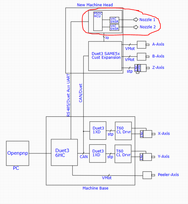
My solution is to use a secondary vacuum sensor board with a dedicated non-Duet mcu to monitor sensor levels and that will set digital io on the Duet inputs. Sensor thresholds will be dynamically set via Openpnp/Duet Aux comm via RS485. Openpnp will simply ask the state of the associated Duet input...
Am I over complicating this? Am I missing a fully native Duet solution?
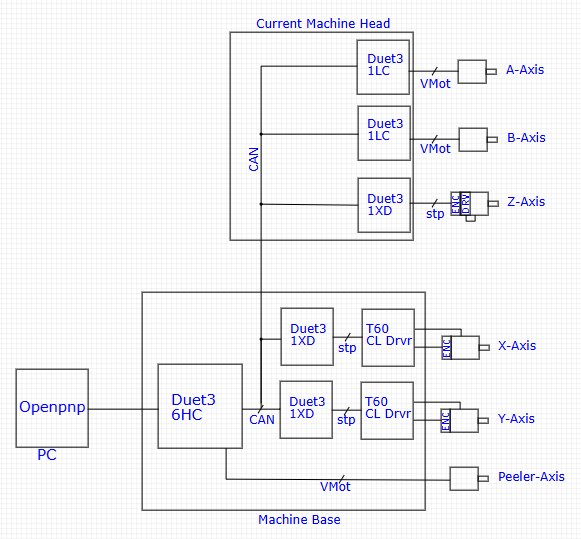
Current Duet based machine
New Duet based machine, Vacumm sensor board in question
Any input appreciated
-
RE: LIS3D using SPI issuesposted in Firmware developers
@dc42 Ah ok, I thought any digital input simply had to be assigned a unique 0-15 Exint. Makes sense now. Ill review the DS and see if I can sort it out.
Thanks for the help
-
RE: LIS3D using SPI issuesposted in Firmware developers
I got it sorted :). I was suspecting the INT pin irq was not getting called because both of my newly declared io0 and io1 pins aren't getting flagged in OM. I tried setting other gpio as inputs and the first pin I found that the OM would flag I set to the LIS3 INT1 and now everything works;
/** Doesnt work **//
//constexpr Pin Lis3dhInt1Pin = PortAPin(12);
//{ TcOutput::none,	TccOutput::tcc1_2F,	AdcInput::none,		SercomIo::none,		sercom2cPad0,		4,	nullptr 	}, // PA12

/** Works! **//
constexpr Pin Lis3dhInt1Pin = PortBPin(3);
{ TcOutput::none,	TccOutput::none,	AdcInput::adc0_15,	SercomIo::sercom5d,	SercomIo::none,		3,	nullptr		},// PB03
The proof
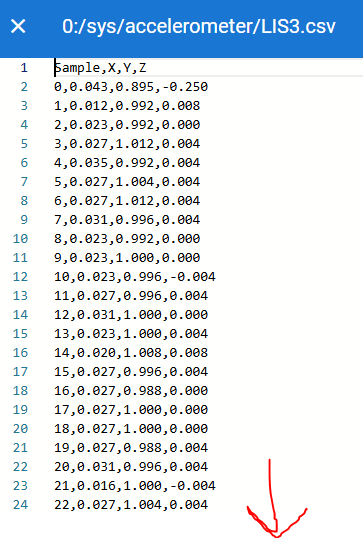
Now I just have to sort out what is going in the config.h, with none of my inputs working as I initally set. All the outputs work fine.
Any rate pleased to announce Duet3Exp SPI works
Thanks for the help guys! -
RE: LIS3D using SPI issuesposted in Firmware developers
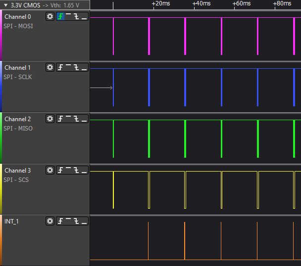
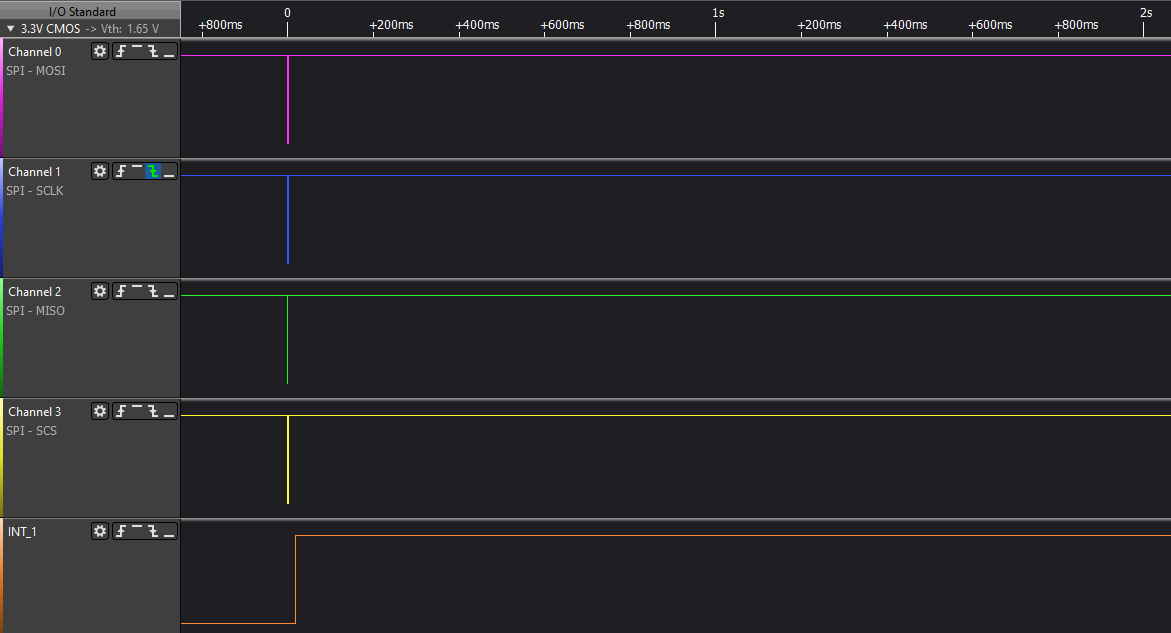
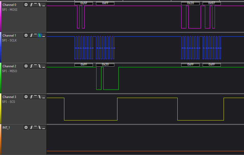
I still not getting any data in the accelerometer files. But Im pretty confident in the sam to lis3 spi comm. Heres some screen grabs of the comm. Im not familiar with accelerometers or this chip so I need to review. One thing I do notice is INT1 is staying high. I would assume this should be cleared once the sam reads the data.
Anyrate heres what I'm seeing;
Boot, post pwr reset of the 6HC and 1HCL;
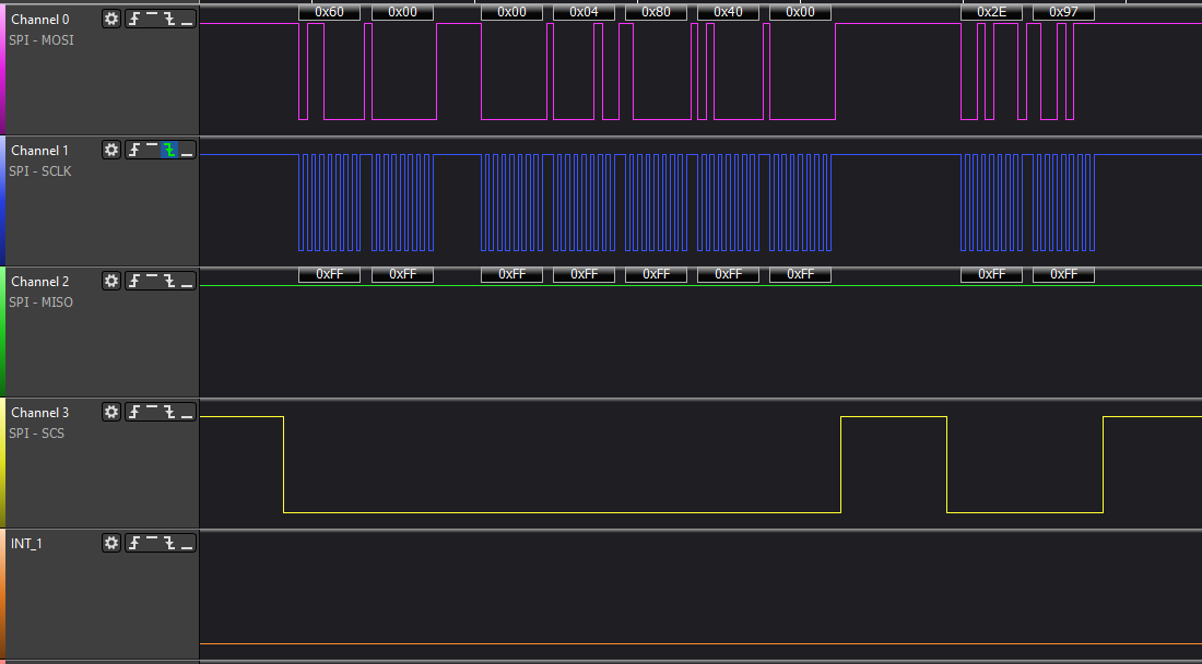
Get data
compressed
expanded
Logs
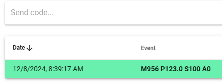
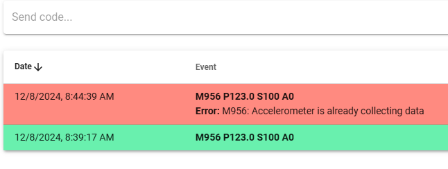
Once I do the M956 command, I am unable to repeat the command;
-
RE: LIS3D using SPI issuesposted in Firmware developers
@dc42
Ok, thanks for the info. I'll give testing on the bread board a go now that I have that working. I have 2 diff BOBs that both supposedly support i2C and SPI. I only chose spi on personal preference. If it becomes too difficult to implement Ill revert back i2C.Thank you
-
RE: Custom 1HCL HW/FW bootloader issuesposted in Firmware developers
@dc42
1, point taken and thank you for the heads up.
2, yes this is by design
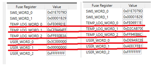
3, I presumed as much, thanks for confirming as I was having trouble following the revs to understand the relationshipI finally got a blank chip flashed and running w the bootloader and able to tie into the Duet CAN system. The issue was improper fuse setting. To fix I simply set the USER_WORD_x fuses as I read from the OE 1HCL chip;
USER_WORD_0 = 0xFE9AE239 (valid)
USER_WORD_1 = 0xAEECFFB1 (valid)
USER_WORD_2 = 0xFFFFFFFF (valid)
This is good because I can now debug on the bread board which I can't do in circuit. I proceeded to order my untested circuit because I couldn't get the bootloader to work on the breadboard. I thought this was because the chip carriers got don't have a provision for the bottom solder pad. I assumed that pad was an essential ground that when missing was causing all of my problems. Fortunately not the case.
Thanks for the help David!
-
RE: LIS3D using SPI issuesposted in Firmware developers
@dc42
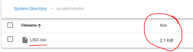
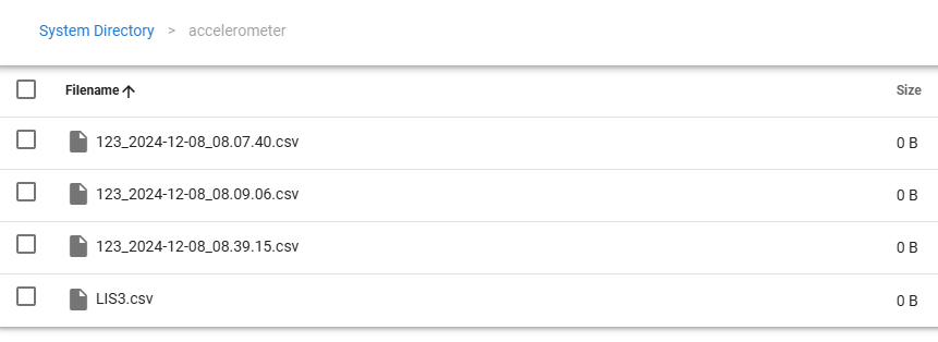
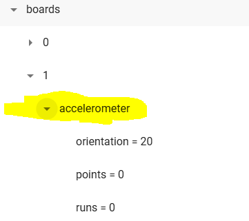
hmm doesn't appear to be working. I am able to set the command and create the .csv file, but the file stays empty;
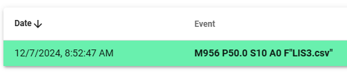
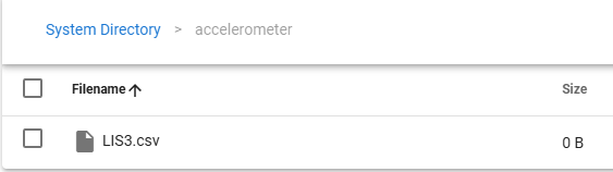
Here is the config setup
M955 P50.0 I20
;M955 P50.0 C"spi.cs1+spi.cs0" I10 ; configure accelerometer on exp using SPI pins and specify orientation
Again, this is custom FW on custom HW. I'm fairly confident in the HW. Not so confident in my FW config.
I have set things for;- x3 dumb drivers; all 3 step signals working but dir on driver2 not working, HW correctly ohms out
- x2 outs; all work
- x2 io inputs; appear functional but not working as expected. Input changes are not reflected in the OM. I'm sure the HW is wired correctly as setting them as pullup via config '^' pulls them to vddd otherwise, they float.
- x1 spi for LIS3. under review
Here the FW config
#if SUPPORT_LIS3DH

# if SUPPORT_I2C_SENSORS

#  define ACCELEROMETER_USES_SPI			(0)				// accelerometer is connected via I2C
constexpr Pin Lis3dhInt1Pin = PortAPin(20);					// same as io1.in

# else

#  define ACCELEROMETER_USES_SPI			(1)				// accelerometer is connected via SPI
constexpr Pin Lis3dhCsPin = PortAPin(18);					// same as encoder CS pin
constexpr Pin Lis3dhInt1Pin = PortAPin(12);					// same as io1.in

# endif

#endif

// Shared SPI (used for interface to encoders, not for temperature sensors)
constexpr uint8_t SspiSercomNumber = 1;
constexpr uint32_t SspiDataInPad = 3;
constexpr Pin SSPIMosiPin = PortAPin(16);
constexpr GpioPinFunction SSPIMosiPinPeriphMode = GpioPinFunction::C;

constexpr Pin SSPISclkPin = PortAPin(17);
constexpr GpioPinFunction SSPISclkPinPeriphMode = GpioPinFunction::C;

constexpr Pin SSPIMisoPin = PortAPin(19);
constexpr GpioPinFunction SSPIMisoPinPeriphMode = GpioPinFunction::C;

//**REMAPPED we use the decoder pins for other things
// Position decoder
//constexpr Pin PositionDecoderPins[] = { PortAPin(24), PortAPin(25), PortBPin(22) };
//constexpr GpioPinFunction PositionDecoderPinFunction = GpioPinFunction::G;

// Clock generator pin for TMC2160
constexpr uint8_t ClockGenGclkNumber = 5;
constexpr Pin ClockGenPin = PortBPin(11);
constexpr GpioPinFunction ClockGenPinPeriphMode = GpioPinFunction::M;

// Brake On pin for version 2.0 board. If the BrakwPwmPort is configured as the brake pin in M569.7 then the BrakeOnPin is used implicitly as well.
//**REMAPP**//constexpr Pin BrakePwmPin = PortBPin(10);
//**REMAPP**//constexpr Pin BrakeOnPin = PortAPin(20);

constexpr auto sercom2cPad0 = SercomIo::sercom2c + SercomIo::pad0;
constexpr auto sercom2cPad1 = SercomIo::sercom2c + SercomIo::pad1;

// Table of pin functions that we are allowed to use
constexpr PinDescription PinTable[] =
{
	//	TC					TCC					ADC					SERCOM in			SERCOM out	  Exint PinName
	// Port A
//	{ TcOutput::none,	TccOutput::none,	AdcInput::none,		SercomIo::none,		SercomIo::none,		0,	"spi.cs1"		},	// PA00 CAN reset jumper on V0 boards, spi.cs1 on V1 boards
	{ TcOutput::none,	TccOutput::none,	AdcInput::none,		SercomIo::none,		SercomIo::none,		0,	nullptr			},	// PA00 //**REMAPPED CAN RST**//
//	{ TcOutput::tc2_1,	TccOutput::none,	AdcInput::none,		SercomIo::none,		SercomIo::none,		Nx,	"out0"			},	// PA01 OUT0 /**REMAPP**/
	{ TcOutput::tc2_1,	TccOutput::none,	AdcInput::none,		SercomIo::none,		SercomIo::none,		Nx,	nullptr			},	// PA01 //**REMAPPED**//
	{ TcOutput::none,	TccOutput::none,	AdcInput::adc0_0,	SercomIo::none,		SercomIo::none,		Nx,	"ate.vin"		},	// PA02 VIN monitor
	{ TcOutput::none,	TccOutput::none,	AdcInput::adc0_1,	SercomIo::none,		SercomIo::none,		Nx, nullptr			},	// PA03 board type
	{ TcOutput::none,	TccOutput::none,	AdcInput::adc0_4,	SercomIo::none,		SercomIo::none,		Nx,	nullptr			},	// PA04 VREF_MON
	{ TcOutput::none,	TccOutput::none,	AdcInput::none,		SercomIo::none,		SercomIo::none,		Nx,	nullptr			},	// PA05 driver ENN
	{ TcOutput::none,	TccOutput::none,	AdcInput::adc0_6,	SercomIo::none,		SercomIo::none,		Nx,	"ate.v12"		},	// PA06 12v monitor
//	{ TcOutput::none,	TccOutput::none,	AdcInput::adc0_7,	SercomIo::none,		SercomIo::none,		7,	"temp1"			},	// PA07 TEMP1 /**REMAPP**/
	{ TcOutput::none,	TccOutput::none,	AdcInput::none,		SercomIo::none,		SercomIo::none,		Nx,	nullptr			},  // PA07 //**REMAPPED driver2 DIR**//
//	{ TcOutput::none,	TccOutput::none,	AdcInput::none,		SercomIo::none,		SercomIo::none,		Nx,	nullptr			},	// PA08 driver MOSI /**REMAPP**/
	{ TcOutput::none,	TccOutput::none,	AdcInput::none,		SercomIo::none,		SercomIo::none,		Nx,	"out1"			},	// PA08 //**REMAPPED out1	**//
//	{ TcOutput::none,	TccOutput::none,	AdcInput::none,		SercomIo::none,		SercomIo::none,		Nx,	nullptr			},	// PA09 driver SCLK /**REMAPP**/
	{ TcOutput::none,	TccOutput::none,	AdcInput::none,		SercomIo::none,		SercomIo::none,		Nx,	"out0"			},	// PA09 //**REMAPPED "out0" **//
//	{ TcOutput::none,	TccOutput::none,	AdcInput::none,		SercomIo::none,		SercomIo::none,		Nx,	nullptr			},	// PA10 driver CS /**REMAPP**/
	{ TcOutput::none,	TccOutput::none,	AdcInput::none,		SercomIo::none,		SercomIo::none,		13,	"io1.in"		},	// PA10 driver CS //**REMAPPED "io1.in"**//
//	{ TcOutput::none,	TccOutput::none,	AdcInput::none,		SercomIo::none,		SercomIo::none,		Nx,	nullptr			},	// PA11 driver MISO /**REMAPP**/
	{ TcOutput::none,	TccOutput::none,	AdcInput::none,		SercomIo::none,		SercomIo::none,		3,	"io0.in"		},	// PA11 driver MISO //**REMAPPED "io0.in"**//
//	{ TcOutput::none,	TccOutput::tcc1_2F,	AdcInput::none,		SercomIo::none,		sercom2cPad0,		Nx,	"io1.out" 		},	// PA12 IO1 out, I2C capable /**REMAPP**/
	{ TcOutput::none,	TccOutput::tcc1_2F,	AdcInput::none,		SercomIo::none,		sercom2cPad0,		1,	nullptr 		},	// PA12 //**REMAPPED ACCEL_INT**//
//	{ TcOutput::none,	TccOutput::none,	AdcInput::none,		sercom2cPad1,		SercomIo::none,		13,	"io1.in"		},	// PA13 IO1 in, I2C capable /**REMAPP**/
	{ TcOutput::none,	TccOutput::none,	AdcInput::none,		sercom2cPad1,		SercomIo::none,		Nx,	nullptr			},	// PA13 //**REMAPPED 	**//
	{ TcOutput::none,	TccOutput::none,	AdcInput::none,		SercomIo::none,		SercomIo::none,		Nx,	nullptr			},	// PA14 crystal
	{ TcOutput::none,	TccOutput::none,	AdcInput::none,		SercomIo::none,		SercomIo::none,		Nx,	nullptr			},	// PA15 crystal
	{ TcOutput::none,	TccOutput::none,	AdcInput::none,		SercomIo::none,		SercomIo::none,		Nx,	nullptr			},	// PA16 AS5047/SPI MOSI (SERCOM1.0)
	{ TcOutput::none,	TccOutput::none,	AdcInput::none,		SercomIo::none,		SercomIo::none,		Nx,	nullptr			},	// PA17 AS5047/SPI SCK (SERCOM1.1)
	{ TcOutput::none,	TccOutput::none,	AdcInput::none,		SercomIo::none,		SercomIo::none,		2,	"spi.cs0,ate.spi.cs" },	// PA18 AS5047/SPI CS (SERCOM1.2)
	{ TcOutput::none,	TccOutput::none,	AdcInput::none,		SercomIo::none,		SercomIo::none,		Nx,	nullptr			},	// PA19 AS5047/SPI MISO (SERCOM1.3)
//	{ TcOutput::none,	TccOutput::none,	AdcInput::none,		SercomIo::none,		SercomIo::none,		Nx,	"pa20,brake.pos"},	//**REMAPP**// // PA20 test pad/spare on V1, Brake On on V2
	{ TcOutput::none,	TccOutput::none,	AdcInput::none,		SercomIo::none,		SercomIo::none,		Nx,	nullptr			},  // PA20 //**REMAPPED driver1 EN** //
//	{ TcOutput::none,	TccOutput::none,	AdcInput::none,		SercomIo::none,		SercomIo::none,		5,	"ate.d0.diag"	},	// PA21 driver DIAG /**REMAPP**/
	{ TcOutput::none,	TccOutput::none,	AdcInput::none,		SercomIo::none,		SercomIo::none,		Nx,	nullptr			},	// PA21 //**REMAPPED**//
	{ TcOutput::none,	TccOutput::none,	AdcInput::none,		SercomIo::none,		SercomIo::none,		Nx,	nullptr			},	// PA22 CAN0 Tx
	{ TcOutput::none,	TccOutput::none,	AdcInput::none,		SercomIo::none,		SercomIo::none,		Nx,	nullptr			},	// PA23 CAN0 Rx
//	{ TcOutput::none,	TccOutput::none,	AdcInput::none,		SercomIo::none,		SercomIo::none,		8,	"pdec.a"		},	// PA24 PDEC0 /**REMAPP**/
	{ TcOutput::none,	TccOutput::none,	AdcInput::none,		SercomIo::none,		SercomIo::none,		Nx,	nullptr			},	// PA24 //**REMAPPED  driver1 DIR**//
//	{ TcOutput::none,	TccOutput::none,	AdcInput::none,		SercomIo::none,		SercomIo::none,		9,	"pdec.b"		},	// PA25 PDEC1 /**REMAPP**/
	{ TcOutput::none,	TccOutput::none,	AdcInput::none,		SercomIo::none,		SercomIo::none,		Nx,	nullptr			},	// PA25	//**REMAPPED  driver0 EN**//
	{ TcOutput::none,	TccOutput::none,	AdcInput::none,		SercomIo::none,		SercomIo::none,		Nx,	nullptr			},	// PA26 not on chip
//	{ TcOutput::none,	TccOutput::none,	AdcInput::none,		SercomIo::none,		SercomIo::none,		Nx,	"ate.d0.dir"	},	// PA27 driver DIR /**REMAPP**/
	{ TcOutput::none,	TccOutput::none,	AdcInput::none,		SercomIo::none,		SercomIo::none,		Nx,	nullptr			},	// PA27 //**REMAPPED  driver0 DIR**//
	{ TcOutput::none,	TccOutput::none,	AdcInput::none,		SercomIo::none,		SercomIo::none,		Nx,	nullptr			},	// PA28 not on chip
	{ TcOutput::none,	TccOutput::none,	AdcInput::none,		SercomIo::none,		SercomIo::none,		Nx,	nullptr			},	// PA29 not on chip
	{ TcOutput::none,	TccOutput::none,	AdcInput::none,		SercomIo::none,		SercomIo::none,		Nx,	nullptr			},	// PA30 swclk and LED0
	{ TcOutput::none,	TccOutput::none,	AdcInput::none,		SercomIo::none,		SercomIo::none,		Nx,	nullptr			},	// PA31 swdio and LED1

	// Port B
	{ TcOutput::none,	TccOutput::none,	AdcInput::none,		SercomIo::none,		SercomIo::none,		Nx,	nullptr			},	// PB00 not on chip
	{ TcOutput::none,	TccOutput::none,	AdcInput::none,		SercomIo::none,		SercomIo::none,		Nx,	nullptr			},	// PB01 not on chip
//	{ TcOutput::none,	TccOutput::tcc2_2F,	AdcInput::none,		SercomIo::none,		SercomIo::sercom5d,	Nx,	"io0.out"		},	// PB02 IO0 out, UART available /**REMAPP**/
	{ TcOutput::none,	TccOutput::tcc2_2F,	AdcInput::none,		SercomIo::none,		SercomIo::sercom5d,	Nx,	nullptr			},	// PB02	//**REMAPPED  driver2 EN**//
//	{ TcOutput::none,	TccOutput::none,	AdcInput::adc0_15,	SercomIo::sercom5d,	SercomIo::none,		3,	"io0.in"		},	// PB03 IO0 in, UART available /**REMAPP**/
	{ TcOutput::none,	TccOutput::none,	AdcInput::adc0_15,	SercomIo::sercom5d,	SercomIo::none,		Nx,	nullptr			},	// PB03	//**REMAPPED**//
	{ TcOutput::none,	TccOutput::none,	AdcInput::none,		SercomIo::none,		SercomIo::none,		Nx,	nullptr			},	// PB04 not on chip
	{ TcOutput::none,	TccOutput::none,	AdcInput::none,		SercomIo::none,		SercomIo::none,		Nx,	nullptr			},	// PB05 not on chip
	{ TcOutput::none,	TccOutput::none,	AdcInput::none,		SercomIo::none,		SercomIo::none,		Nx,	nullptr			},	// PB06 not on chip
	{ TcOutput::none,	TccOutput::none,	AdcInput::none,		SercomIo::none,		SercomIo::none,		Nx,	nullptr			},	// PB07 not on chip
//	{ TcOutput::none,	TccOutput::none,	AdcInput::adc0_2,	SercomIo::none,		SercomIo::none,		Nx,	"temp0"			},	// PB08 TEMP0	//**REMAPP**//
	{ TcOutput::none,	TccOutput::none,	AdcInput::adc0_2,	SercomIo::none,		SercomIo::none,		Nx,	nullptr			},	// PB08 //**REMAPPED  driver2 step**//
	{ TcOutput::none,	TccOutput::none,	AdcInput::adc0_3,	SercomIo::none,		SercomIo::none,		Nx,	nullptr			},	// PB09 VSSA monitor
//	{ TcOutput::none,	TccOutput::tcc0_4F,	AdcInput::none,		SercomIo::none,		SercomIo::none,		Nx,	"out1,brake,brake.neg"	},	// PB10 OUT1 //**REMAPP**//
	{ TcOutput::none,	TccOutput::tcc0_4F,	AdcInput::none,		SercomIo::none,		SercomIo::none,		Nx,	nullptr			},	// PB10 OUT1 //**REMAPP**//
	{ TcOutput::none,	TccOutput::none,	AdcInput::none,		SercomIo::none,		SercomIo::none,		Nx,	nullptr			},	// PB11 CLKOUT
	{ TcOutput::none,	TccOutput::none,	AdcInput::none,		SercomIo::none,		SercomIo::none,		Nx,	nullptr			},	// PB12 not on chip
	{ TcOutput::none,	TccOutput::none,	AdcInput::none,		SercomIo::none,		SercomIo::none,		Nx,	nullptr			},	// PB13 not on chip
	{ TcOutput::none,	TccOutput::none,	AdcInput::none,		SercomIo::none,		SercomIo::none,		Nx,	nullptr			},	// PB14 not on chip
	{ TcOutput::none,	TccOutput::none,	AdcInput::none,		SercomIo::none,		SercomIo::none,		Nx,	nullptr			},	// PB15 not on chip
	{ TcOutput::none,	TccOutput::none,	AdcInput::none,		SercomIo::none,		SercomIo::none,		Nx,	nullptr			},	// PB16 not on chip
	{ TcOutput::none,	TccOutput::none,	AdcInput::none,		SercomIo::none,		SercomIo::none,		Nx,	nullptr			},	// PB17 not on chip
	{ TcOutput::none,	TccOutput::none,	AdcInput::none,		SercomIo::none,		SercomIo::none,		Nx,	nullptr			},	// PB18 not on chip
	{ TcOutput::none,	TccOutput::none,	AdcInput::none,		SercomIo::none,		SercomIo::none,		Nx,	nullptr			},	// PB19 not on chip
	{ TcOutput::none,	TccOutput::none,	AdcInput::none,		SercomIo::none,		SercomIo::none,		Nx,	nullptr			},	// PB20 not on chip
	{ TcOutput::none,	TccOutput::none,	AdcInput::none,		SercomIo::none,		SercomIo::none,		Nx,	nullptr			},	// PB21 not on chip
//	{ TcOutput::none,	TccOutput::none,	AdcInput::none,		SercomIo::none,		SercomIo::none,		6,	"pdec.n"		},	// PB22 PDEC2
	{ TcOutput::none,	TccOutput::none,	AdcInput::none,		SercomIo::none,		SercomIo::none,		Nx,	nullptr			},	// PB22 //**REMAPPED  driver1 step**//
//	{ TcOutput::none,	TccOutput::none,	AdcInput::none,		SercomIo::none,		SercomIo::none,		Nx,	"ate.d0.step"	},	// PB23 driver STEP
	{ TcOutput::none,	TccOutput::none,	AdcInput::none,		SercomIo::none,		SercomIo::none,		Nx,	nullptr			},	// PB23 //**REMAPPED  driver0 step**//
};

static constexpr size_t NumPins = ARRAY_SIZE(PinTable);
static constexpr size_t NumRealPins = 32 + 24;			// 32 pins on port A (some missing), 24 on port B
static_assert(NumPins == NumRealPins);					// no virtual pins in this table
Thanks for the help on this
-
RE: LIS3D using SPI issuesposted in Firmware developers
@dc42
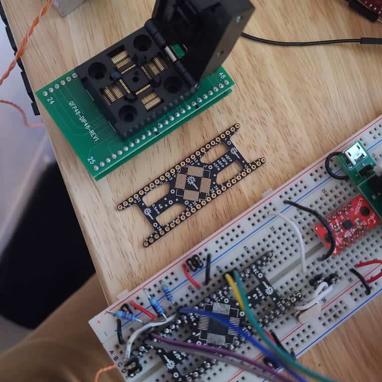
I got the custom main FW running on the custom PCB and Looks like the lis3d chip is chatting w the mcu via spi. How do I bench test the lis3 functioning? I briefly tried the DWC input shaper plugin, but it complains about the machine not being homed. There are no kinematics/limits hooked up at the moment I just want to confirm on the bench the HW/FW are really working. How do I go about this?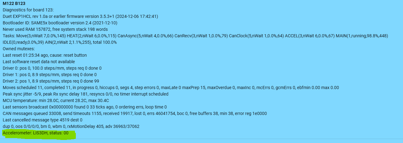
Thanks for any help guys
-
RE: Custom 1HCL HW/FW bootloader issuesposted in Firmware developers
After transfering the Duet 1HCL chip onto my custom pcb I was able to boot load my custom main FW and it mostly works as expected as an CAN expansion node.
I still don't know what is going on with the bootlaoder FW not working on the blank chip. After comparing the Boot FW 2.4 to 2.11 I wasn't coming to any conclusions and I impulsively swapped the OE Deut chip out for my blank chip to see if the 2.4 Boot FW would make a difference. Still no worky
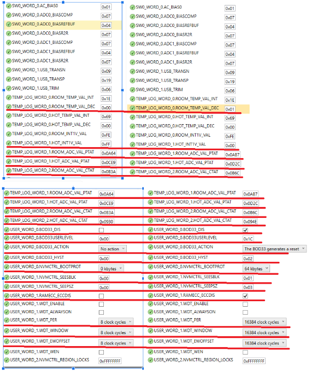
 I know the custom HW is fine and the Bootloader FW ver doesnt seem to make a difference so it must be the fuses. Before I swapped the mcus the last go I took screen shots at the fuse settings. They appear different, but I dont know what or how to interpret them or if it is imperative that they match exactly.
Heres a comparison of the blank chip fuse setting on the L and the Duet 1HCL chip on the R. the different values are underscored red. Should I just set them to match? If anyone has any advice on setting the fuses would be greatly appreciated
Thank You
-
RE: Custom 1HCL HW/FW bootloader issuesposted in Firmware developers
So I got antsy and have some 1HCLs laying around. I pulled the mcu from the OE 1HCL and swapped it into my custom board. The CAN now works and DWC and OM is working. I noticed the Bootloader FW is different than what I was attempting to use.
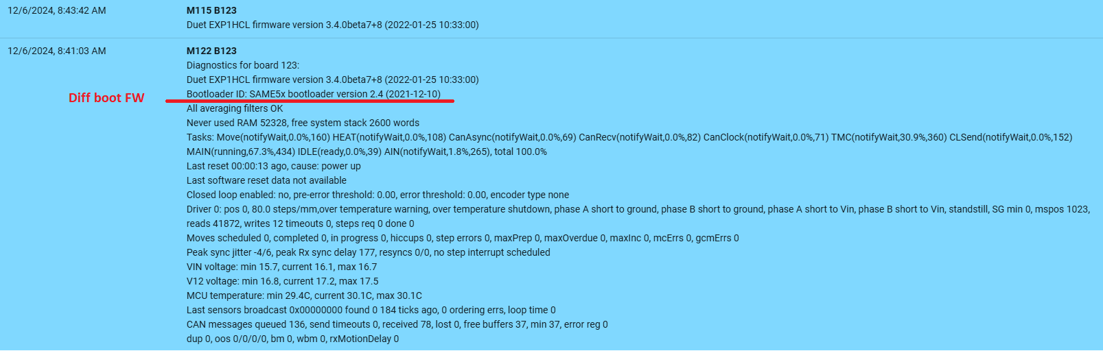
I looked up the 2.4 Bootloader and the readme states there is 1HCL specific changes in this the 2.4 ver. I never thought to look past 2.11 as it's the 'latest'. Any rate I'll work on getting my custom main fw on and see how it all goes...
Thanks guys
-
Custom 1HCL HW/FW bootloader issuesposted in Firmware developers
I made a custom circuit based on the ATSAME51G19A/1HCL. I have the mcu in circuit and have programmed it with SAME_5x v2.11 with nEDBG programmer in Microchip Studio. The chip was erased, fuses set and memory flashed as outlined in the Duet update bootloader faq. Erasing and flashing the chip went fine as verified in Studio.
Ive attached the custom board to a 6HC via CAN cycled the power several times and Im still not getting any fw update requests in DWC or seeing any other boards attached in the OM. I put a logic analyzer on the custom board CAN rx line and are getting msgs, but the tx is sitting idle/high. The circuit follows the Duet 1HCL circuit in regard to OSC, CAN, Board type and SWD so I didn't think there is anything to change in the Bootloader FW config.
I did look at the SAME_5x v2.11 config file and noticed there's a 3-bit binary board type scheme, but no analog board type scheme as the 1HCL appears to use. Anyway, I don't know if that is imperative but can't see any other reason why I can get mcu running with bootloader.
Schematic of circuit attached, any help is much appreciated
Schematic_PNP_Head_2024-12-05 (1).pdf -
M261.2: UART read output findingsposted in General Discussion
Just an Fyi re the new M260.2/M261.2 commands in RRF 3.6. I was stuck for a couple days trying to leverage the 6HC Aux comm port to get/set parameters of a foc motor and report them back to Openpnp via the Main comm port.
Im sending/receiving data on the Aux port as;
M260.2 P1 B{0x52, 0x5A, 0x0D}
G4 10
M261.2 P1 B6
The expected Rx data on the Main port is simply a byte array;
{0x5a, 0x65, 0x72, 0x6f,0x3a, 0x5a}M261.2 indeed reports the data to the Main comm port, but is prepended with" Received (hex) " and the rx bytes are space seperated; ' ' ;
2024-11-25 22:38:29.200 GcodeDriver$ReaderThread TRACE:
[GcodeAsyncDriver:COM13] << Received (hex) 5a 65 72 6f 3a 5a
This needs to be understood, but not explicitly stared in M261.2 if anyone is planning to parse the rx data as one would using regex. For my application the regex
^.*( [0-9a-f]{2}){5} (?<Value>[0-9a-f]{2})Groups the correct Value for me.
Any rate the new commands work great now that I understand the output.