@rjenkinsgb Thanks, I did follow that page and I have the printer homing and running the G32 calibration just fine (please open the vid I originally posted). I just wanted to make sure that the #'s I entered in the config tool were correct and I would get accurate prints.
Posts made by troy_proffitt
-
RE: Need help with Delta Config settingsposted in Tuning and tweaking
-
RE: Need help with Delta Config settingsposted in Tuning and tweaking
@alankilian Yes, I did use the Configuration Tool, But I was bit confused about certain values:
- Delta Radius ?
- Minimum Z ?
- Homed Height ?
- Printable Radius (340/2 I think)?
- Diagonal Rod length (400.3)
- Maximum Carriage Travel (840?)
I'm using a Duet WIFI 2, and updated Firmware through DWC last night to most current. I'll provide the JSON when I get home from work tonight if that helps.
Thanks,
-Troy -
Need help with Delta Config settingsposted in Tuning and tweaking
I am in the process of building a new Delta printer and need some help with my settings. Here are the specs:
- 400.3mm Haydn Magnetic Arms
- Duet smart effector (and associated linear carriages)
- Bed size - 340mm
- Build Height is 840mm
Everything is wired up and I can run the calibration G32 (Here is a vid).
I haven't added an extruder yet, but I would appreciate some affirmation that my settings are correct.
Thanks for your help.
-Troy -
RE: Trigger servo movement after 1st layerposted in General Discussion
I ended up teaching my self some basic Python and wrote a script myself. Hopefully this will help others that are wanting to use a CPAP fan or other servo type fan signals:
-
RE: Trigger servo movement after 1st layerposted in General Discussion
I've submitted a request in the CURA forum to have someone possibly help modify a post processing script to add the M42 command. Hopefully I can get some direction since I've never worked with Python syntax before:
If anyone on this forum is familiar with CURA post processing, I'd appreciate the help!
-Troy
-
RE: Trigger servo movement after 1st layerposted in General Discussion
Is this something that could be added to your beginning gcode (so you don't have to modify each time you want to print something)
The holy grail would be to use a fan speed variable in the slicer and convert tht to the value needed in the M42. For example if I set 75% fan in the slicer, the post -processing code would generate a M42 P9 S0.65, and if I set 50% in the slicer, the code would generate M42 P9 S0.6. If CURA can do an if/elseif similar to Prusa, I think I can figure it out.
Edit, it seems that CURA has a post processing plugin that will do a search / replace based on z height. I'll play around with this and reply back. This is a bit of a hassle, but should solve my problem. Thanks for your help!
-
RE: Trigger servo movement after 1st layerposted in General Discussion
I'd like to trigger M42 P8 S0.5; when the fan turns on.
-
RE: Trigger servo movement after 1st layerposted in General Discussion
I have been researching M581 to possibly monitor the fan pins (since fan turns on after 1st layer). Is this a possibility since i'm using firmware 3.2?
-
Trigger servo movement after 1st layerposted in General Discussion
Is there a way to trigger an M42 command after 1st layer? I know there is a way to add this to the slicer, but I believe it would be less maintenance to add to the Duet.
-
RE: Controlling inexpensive BLDC for cpap part cooling - Duet 3posted in Duet Hardware and wiring
I understand this is an old thread, but I'm trying to do something very similar and was wondering if this could be controlled from a Duet WIFI 2?
-
RE: Suggestions for hight precision CoreXYposted in General Discussion
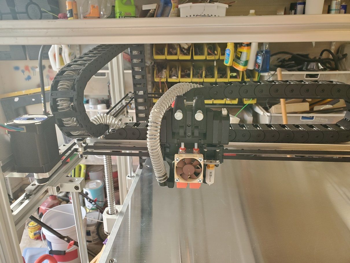
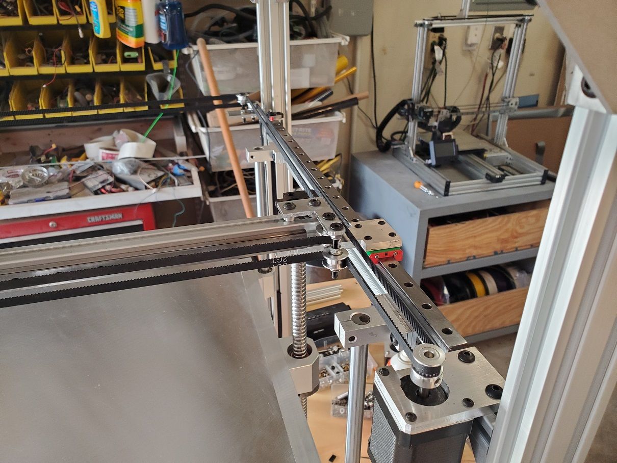
I just finished building a new CoreXY printer with the goal of no 3d printed structural parts at all. The only printed parts are the enclosures for the controller boards and the extruder mount (dual BMG extruders).
I've been 3d printing for several years on both cartesian and corexy. A more rigid printer usually produces better prints. The best improvements were around bed stiffness. I recently went to the 3 independent "true level" setup with a 1/4 thick MIC6 aluminum plate + 1/4 tempered glass. Each z axis motor is controlled by an external stepper and has a 3:1 gear reduction for both higher resolution and higher strength (HERE is a vid of my bed setup). Since this vid, I've added 12mm smooth rods to each ballscrew to improve linear motion.
Attached are a few pics of my printer:

 !
! -
Controlling BLDC board via DuetWIFI PWM signalposted in Duet Hardware and wiring
I am using a 3 phase CPAP blower as my parts cooler on my printer. Right now, I'm using a DC-DC relay to turn it on or off via the fan plug on the duet board. This works great to just turn the fan on/off, but the only way to actually adjust the airflow is via the pot on the BLDC board.
I ordered a new BLDC controller that has the ability to be controlled via PWM and was wondering what pin I can use on the Duet Wifi2 board to control it. I've read on other threads that you can use the fan ground pin? On the BLDC purchase page it says:Speed control signal input (integrated potentiometer for speed control on the board can also be connected to 0-5V analog quantity to support PWM to 0-5 signal input speed control)
Thanks for your help
-
RE: Triple z bed leveling using ext drivers - All you need to knowposted in Duet Hardware and wiring
I used that link extensively, but it didn't paint a full picture for what I needed.
-
RE: Stepper Driver Expansion Module for Duet WiFiposted in Duet Hardware and wiring
I am using THIS driver.
Here is how you wire it using just the expansion header:
ENA - goes to E2_EN on the header
ENA + goes to 3.3v on the header
DIR - goes to ground
DIR + goes to E2_DIR on the header
PUL - goes to ground
PUL + goes to E2_STEP on the header -
Triple z bed leveling using ext drivers - All you need to knowposted in Duet Hardware and wiring
I just recently got the triple z axis bed leveling working. It was a major pain to scour the Duet website / internet to figure out everything you need to do so I thought I'd document everything and put it in a single place. I am already using 2 extruders so my Duet Wifi board by default couldn't handle the 3 steppers I needed so I turned to TB6600 external stepper drivers. I connected them to the board using the expansion header using THIS diagram. Using E2,E3 and E4 Pins.
Here is how you wire them to the external drivers (using the Extruder2 pins):
ENA - goes to E2_EN on the header
ENA + goes to 3.3v on the header
DIR - goes to ground
DIR + goes to E2_DIR on the header
PUL - goes to ground
PUL + goes to E2_STEP on the headerRinse repeat for E3 and E4 pins (I daisy-chained the 3.3v from the header to all 3 external steppers)
Now onto the config.g file. First you have to assign Drives 5-7 (in my case) using M569 and also update your M584 line to use Z5:6:7
M569 P5 R1 T2.5:2.5:5                                                              ; Drive 5 goes forwards
M569 P6 R1 T2.5:2.5:5                                                              ; Drive 6 goes forwards
M569 P7 R1 T2.5:2.5:5                                                              ; Drive 7 goes forwards
M584 X0 Y1 Z5:6:7 E3:4
   ; set drive mapping
The T2.5:2.5:5 part was tricky to figure out. Your external steppers won't do anything till you put that part in.
Where do you find all the assignments for motor #'s? Took me a while to find that, but here it is:
0 - X Axis
1 - Y Axis
2 - Z Axis
3 - E0 Axis
4 - E1 Axis
5 - E2 Axis (Expansion Header)
6 - E3 Axis (Expansion Header)
7 - E4 Axis (Expansion Header)
8 - E5 Axis (Expansion Header)
9 - E6 Axis (Expansion Header)
10 - 10 (LCD_CONN Header)
11 - 11 (LCD_CONN Header)Ok! Now you need add the M671 line to config.g to give the coordinates to each of your leadscrews:
Z1 - X20 Y20
Z2 - X200 Y360
Z3 - X485 Y20M671 X20:200:485 Y20:360:20 S1 ; Leadscrews at rear front, back middle and rear frontLastly you need to update the bed.g file (please note that the order of your leadscrews and the order of probing in bed.g need to be the same)
G30              ; home Z by probing the bed
G30 P0 X20 Y20 Z-99999 ; probe near a leadscrew
G30 P1 X200 Y360 Z-99999 ; probe near a leadscrew
G30 P2 X485 Y20 Z-99999 S3 ; probe near a leadscrew and calibrate 3 motors
I add a single G30 Probe after it homes x/y since it seems to give a reference z height before the actual P0-P2 probes (it raises and lowers the z less for some reason)
So after you add all this, just put the G32 command in your homeall.g instead of the code you originally had for the z and I believe that's all I had to do. Here is a video of mine in action: