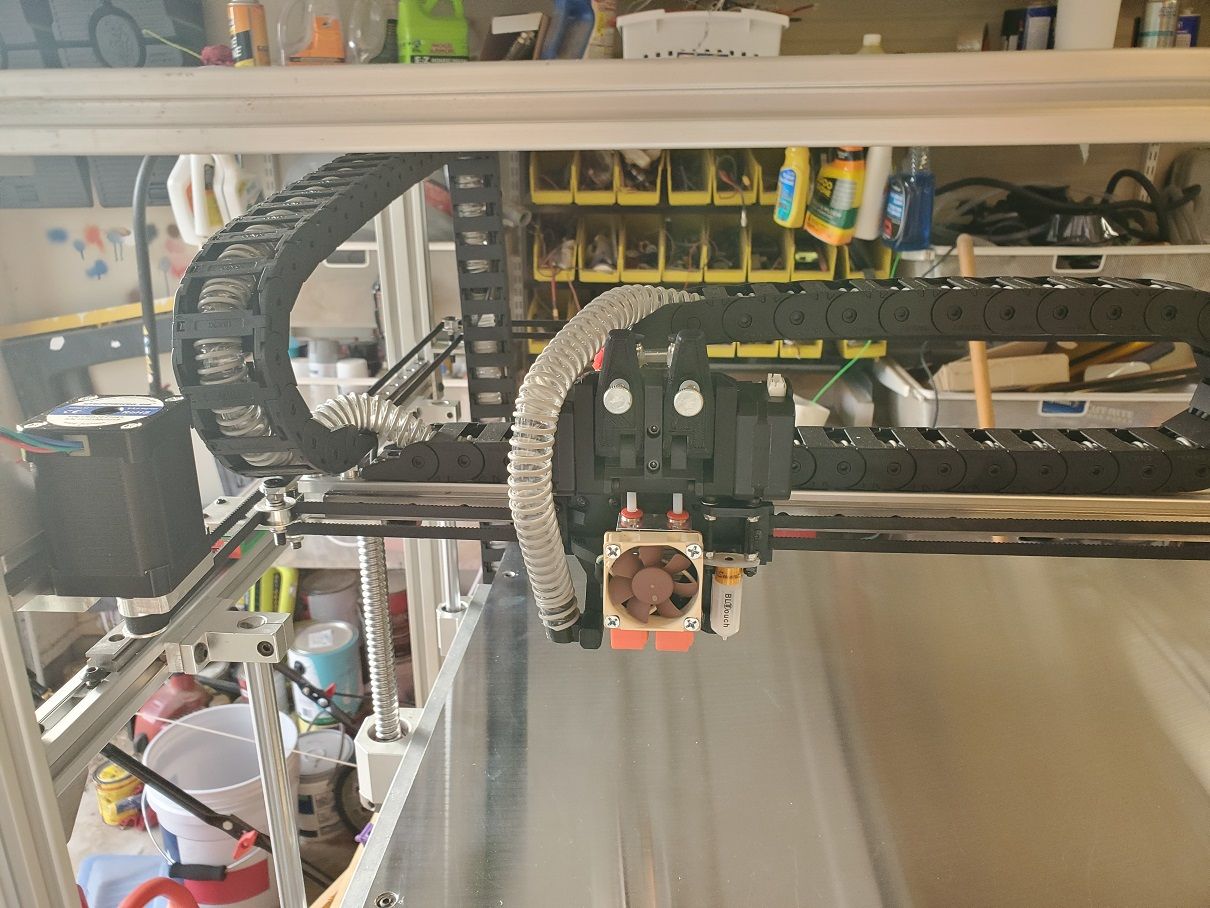
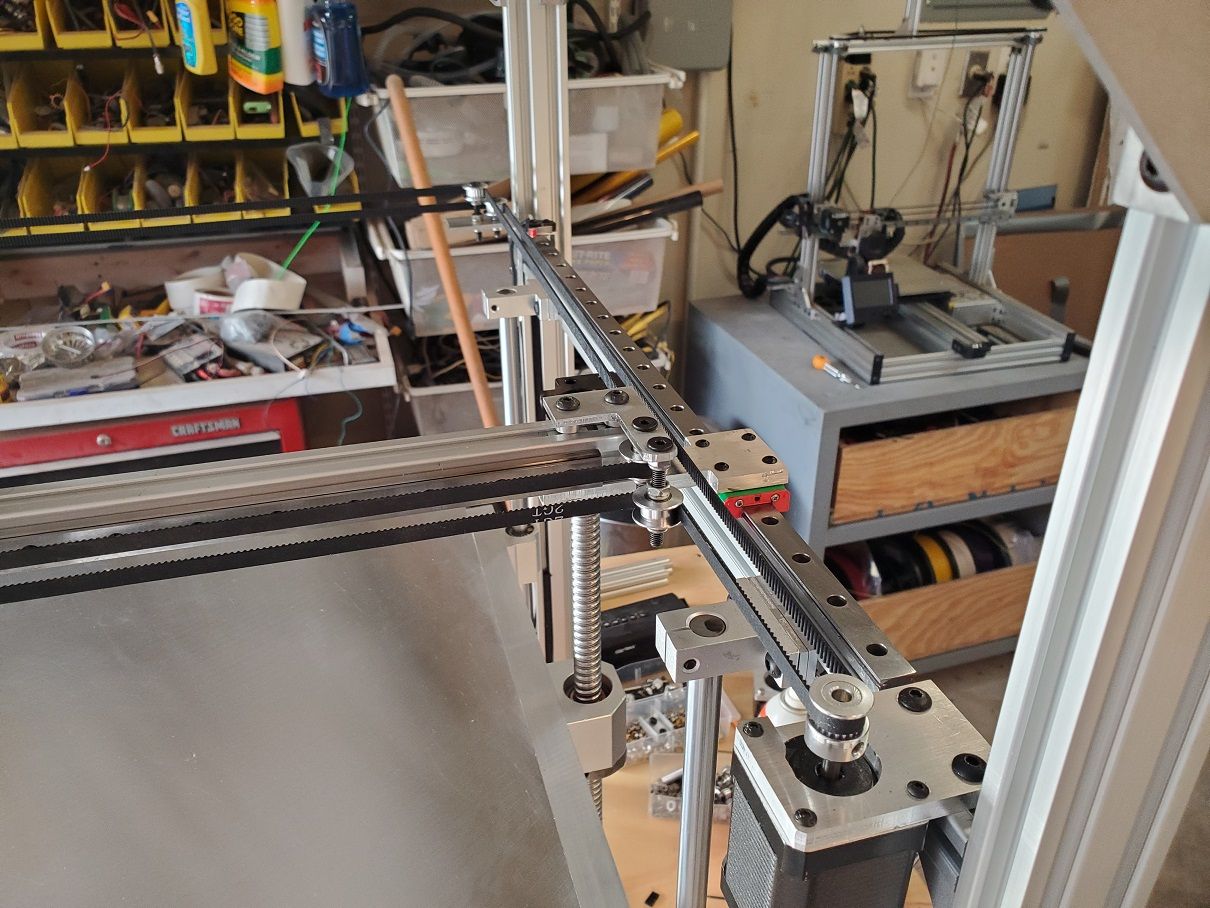
I just recently got the triple z axis bed leveling working. It was a major pain to scour the Duet website / internet to figure out everything you need to do so I thought I'd document everything and put it in a single place. I am already using 2 extruders so my Duet Wifi board by default couldn't handle the 3 steppers I needed so I turned to TB6600 external stepper drivers. I connected them to the board using the expansion header using THIS diagram. Using E2,E3 and E4 Pins.
Here is how you wire them to the external drivers (using the Extruder2 pins):
ENA - goes to E2_EN on the header
ENA + goes to 3.3v on the header
DIR - goes to ground
DIR + goes to E2_DIR on the header
PUL - goes to ground
PUL + goes to E2_STEP on the header
Rinse repeat for E3 and E4 pins (I daisy-chained the 3.3v from the header to all 3 external steppers)
Now onto the config.g file. First you have to assign Drives 5-7 (in my case) using M569 and also update your M584 line to use Z5:6:7
M569 P5 R1 T2.5:2.5:5                                                              ; Drive 5 goes forwards
M569 P6 R1 T2.5:2.5:5                                                              ; Drive 6 goes forwards
M569 P7 R1 T2.5:2.5:5                                                              ; Drive 7 goes forwards
M584 X0 Y1 Z5:6:7 E3:4
   ; set drive mapping
The T2.5:2.5:5 part was tricky to figure out. Your external steppers won't do anything till you put that part in.
Where do you find all the assignments for motor #'s? Took me a while to find that, but here it is:
0 - X Axis
1 - Y Axis
2 - Z Axis
3 - E0 Axis
4 - E1 Axis
5 - E2 Axis (Expansion Header)
6 - E3 Axis (Expansion Header)
7 - E4 Axis (Expansion Header)
8 - E5 Axis (Expansion Header)
9 - E6 Axis (Expansion Header)
10 - 10 (LCD_CONN Header)
11 - 11 (LCD_CONN Header)
Ok! Now you need add the M671 line to config.g to give the coordinates to each of your leadscrews:
Z1 - X20 Y20
Z2 - X200 Y360
Z3 - X485 Y20
M671 X20:200:485 Y20:360:20 S1 ; Leadscrews at rear front, back middle and rear front
Lastly you need to update the bed.g file (please note that the order of your leadscrews and the order of probing in bed.g need to be the same)
G30              ; home Z by probing the bed
G30 P0 X20 Y20 Z-99999 ; probe near a leadscrew
G30 P1 X200 Y360 Z-99999 ; probe near a leadscrew
G30 P2 X485 Y20 Z-99999 S3 ; probe near a leadscrew and calibrate 3 motors
I add a single G30 Probe after it homes x/y since it seems to give a reference z height before the actual P0-P2 probes (it raises and lowers the z less for some reason)
So after you add all this, just put the G32 command in your homeall.g instead of the code you originally had for the z and I believe that's all I had to do. Here is a video of mine in action:
https://www.youtube.com/watch?v=zqdJ47OT_BQ

 !
!