This is sweet!
Posts made by tmeryhew
-
RE: Can’t Pass 250°posted in Tuning and tweaking
I just checked. I’m getting 4.4 ohms across the heater cartridge leads.
So my calculation is 32W at the cartridge.
Also, I rewired it directly to the board, same 250° top end limitation.
-
RE: Can’t Pass 250°posted in Tuning and tweaking
I just pulled out the heater and checked. It’s a 12V 40W heater cartridge.
I would think this should heat up past 250°.
Also, I put a PT1000 sensor in.
-
RE: Can’t Pass 250°posted in Tuning and tweaking
@fcwilt I have a 12V system. The side of the PSU says its rated up to 360 Watts.
As for the the heater cartridge, its the stock one that came with this Cr-10 Mini that I’ve been modifying. I’ll take it apart here in a bit and hopefully the wattage is listed on it somewhere.
Any recommendations on a better PSU and heater cartridge?
-
RE: Can’t Pass 250°posted in Tuning and tweaking
So I was confused about that. I saw something talking about disconnecting the temp sensor from the board and punching in some commands….
I set this up when everything was still on the dozuki. What’s the process for tuning it?
-
RE: Can’t Pass 250°posted in Tuning and tweaking
; Configuration file for Duet WiFi (firmware version 3)
; executed by the firmware on start-up
;
; generated by RepRapFirmware Configuration Tool v3.2.3 on Fri Mar 19 2021 21:41:05 GMT-0700 (MST); General preferences
G90 ; send absolute coordinates...
M83 ; ...but relative extruder moves
M550 P"Genesis" ; set printer name; Network
M551 P"shatner1" ; set password
M552 P0.0.0.0 S1 ; enable network and acquire dynamic address via DHCP
M586 P0 S1 ; enable HTTP
M586 P1 S0 ; disable FTP
M586 P2 S0 ; disable Telnet; Drives
M569 P0 S0 ; physical drive 0 goes backwards
M569 P1 S0 ; physical drive 1 goes backwards
M569 P2 S1 ; physical drive 2 goes forwards
M569 P3 S0 ; physical drive 3 goes backwards
M584 X0 Y1 Z2 E3 ; set drive mapping
M350 X16 Y16 Z16 E16 I1 ; configure microstepping with interpolation
M92 X80.00 Y80.00 Z400.00 E95.00 ; set steps per mm
M566 X900.00 Y900.00 Z100.00 E900.00 ; set maximum instantaneous speed changes (mm/min)
M203 X35000.00 Y35000.00 Z300.00 E10000.00 ; set maximum speeds (mm/min)
M201 X500.00 Y500.00 Z500.00 E5000.00 ; set accelerations (mm/s^2)
M906 X900 Y900 Z900 E800 I30 ; set motor currents (mA) and motor idle factor in per cent
M84 S30 ; Set idle timeout; Axis Limits
M208 X0 Y0 Z0 S1 ; set axis minima
M208 X300 Y220 Z300 S0 ; set axis maxima; Endstops
M574 X1 S1 P"^xstop" ; configure active-high endstop for low end on X via pin ^xstop
M574 Y1 S1 P"^ystop" ; configure active-high endstop for low end on Y via pin ^ystop
M574 Z1 S1 P"^zstop" ; configure active-high endstop for low end on Z via pin ^zstop; Z-Probe
M950 S0 C"exp.heater3" ; create servo pin 0 for BLTouch
M558 P9 C"^zprobe.in" H5 F240 T12000 ; set Z probe type to bltouch and the dive height + speeds
G31 P500 X-45 Y-7 Z3.45 ; set Z probe trigger value, offset and trigger height
M557 X15:215 Y15:195 S40 ; define mesh grid; Heaters
M308 S0 P"bedtemp" Y"thermistor" A"Bed" T98801 B4185 ; configure sensor 0 as thermistor on pin bedtemp
M950 H0 C"bedheat" T0 ; create bed heater output on bedheat and map it to sensor 0
M307 H0 B0 S1.00 ; disable bang-bang mode for the bed heater and set PWM limit
M140 H0 ; map heated bed to heater 0
M143 H0 S100 ; set temperature limit for heater 0 to 100C
M308 S1 P"e0temp" Y"pt1000" ; configure sensor 1 as thermistor on pin e0temp
M950 H1 C"e0heat" T1 ; create nozzle heater output on e0heat and map it to sensor 1
M307 H1 B0 S1.00 ; disable bang-bang mode for heater and set PWM limit
M143 H1 S450 ; set temperature limit for heater 1 to 450C; Fans
M950 F0 C"fan0" Q500 ; create fan 0 on pin fan0 and set its frequency
M106 P0 S0 H-1 ; set fan 0 value. Thermostatic control is turned off
M950 F1 C"fan1" Q500 ; create fan 1 on pin fan1 and set its frequency
M106 P1 S1 H1 T45 ; set fan 1 value. Thermostatic control is turned on; Tools
M563 P0 D0 H1 F0 ; define tool 0
G10 P0 X0 Y0 Z0 ; set tool 0 axis offsets
G10 P0 R0 S0 ; set initial tool 0 active and standby temperatures to 0C; Custom settings are not defined
; Miscellaneous
M501 ; load saved parameters from non-volatile memory
M911 S10 R11 P"M913 X0 Y0 G91 M83 G1 Z3 E-5 F1000" ; set voltage thresholds and actions to run on power loss
T0 ; select first tool -
Can’t Pass 250°posted in Tuning and tweaking
So I installed a Copperhead hot end into my printer. I’m using a Duet 2 ethernet. I went in and changed the temperature parameter to 450 from 250. And now that I’m running the printer up, I can only reach 250 on the hot end.
Any ideas?
-
RE: How is the “Height Map” Used?posted in General Discussion
@Phaedrux Yes it did. It just seems like it performed worse with the mesh compensation on...
-
RE: How is the “Height Map” Used?posted in General Discussion
This first one is with the start code set to G29 S2.

This second picture is when I had it set to G29.

-
RE: How is the “Height Map” Used?posted in General Discussion
@Phaedrux so when I run the test print the second time with G29 S0, should it still probe the bed? Because that is what it's doing right now.
-
RE: How is the “Height Map” Used?posted in General Discussion
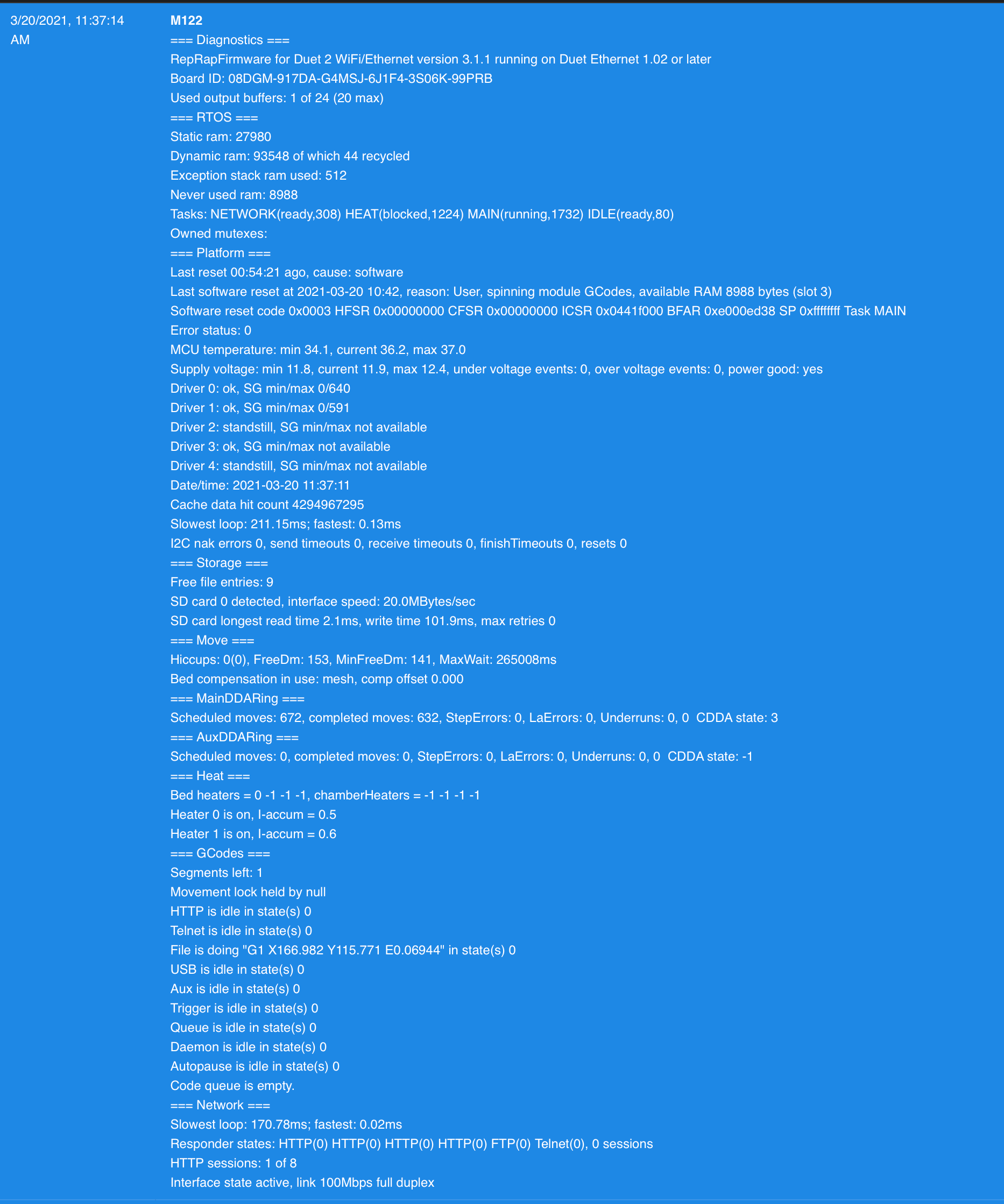
I've gone in and made the changes you describe. I am running the file you sent as we speak. I sent M122 and this was the result.
Should my "comp offset" be 0.000? Does this mean anything?
-
RE: How is the “Height Map” Used?posted in General Discussion
@Phaedrux thank you so much. You guys really know your stuff. I'll go ahead and work on this right now.
How can I save/export all of my settings as a JSON once I have it dialed in?
-
RE: How is the “Height Map” Used?posted in General Discussion
And to clarify, yes it appears to be working. I can definitely generate a height map. Are there other things I should be looking for to confirm its working?
Other than obviously not crashing into the bed.
-
RE: How is the “Height Map” Used?posted in General Discussion
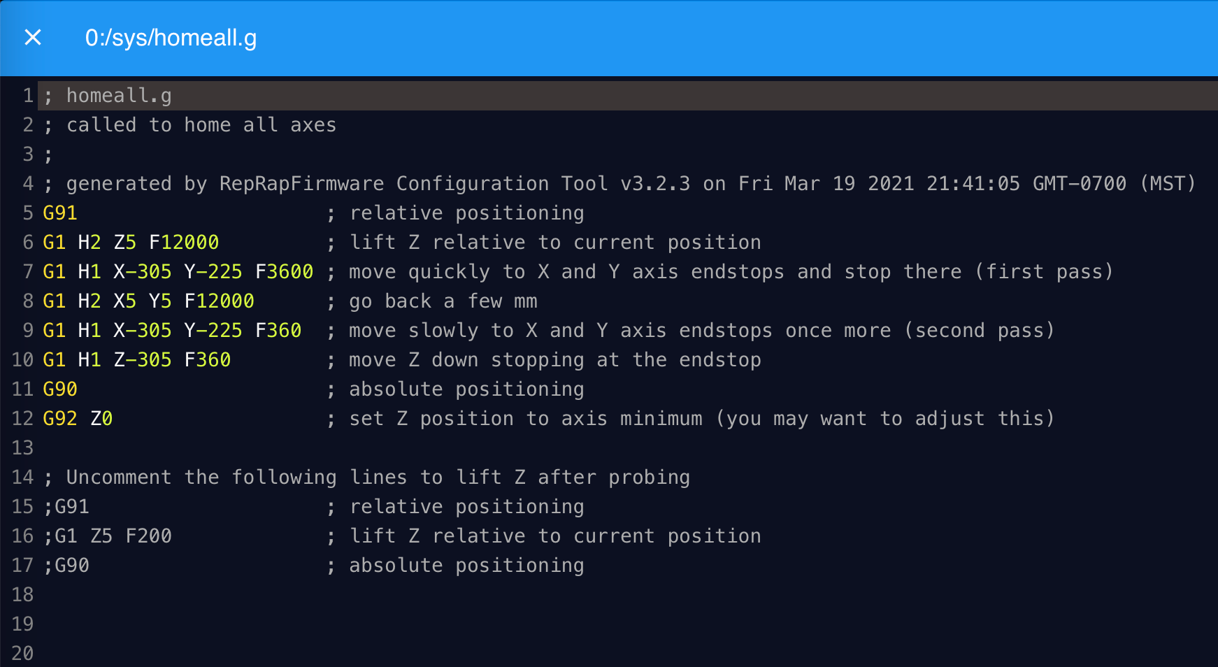
; homeall.g
; called to home all axes
;
; generated by RepRapFirmware Configuration Tool v3.2.3 on Fri Mar 19 2021 21:41:05 GMT-0700 (MST)
G91 ; relative positioning
G1 H2 Z5 F12000 ; lift Z relative to current position
G1 H1 X-305 Y-225 F3600 ; move quickly to X and Y axis endstops and stop there (first pass)
G1 H2 X5 Y5 F12000 ; go back a few mm
G1 H1 X-305 Y-225 F360 ; move slowly to X and Y axis endstops once more (second pass)
G90 ; absolute positioning
G1 X150 Y110 F6000 ; move probe to bed center
G30 ; probe the bed; Uncomment the following lines to lift Z after probing
;G91 ; relative positioning
;G1 Z5 F200 ; lift Z relative to current position
;G90 ; absolute positioning -
RE: How is the “Height Map” Used?posted in General Discussion
; Configuration file for Duet WiFi (firmware version 3) ; executed by the firmware on start-up ; ; generated by RepRapFirmware Configuration Tool v3.2.3 on Fri Mar 19 2021 21:41:05 GMT-0700 (MST) ; General preferences G90 ; send absolute coordinates... M83 ; ...but relative extruder moves M550 P"Genesis" ; set printer name ; Network M551 P"shatner1" ; set password M552 P0.0.0.0 S1 ; enable network and acquire dynamic address via DHCP M586 P0 S1 ; enable HTTP M586 P1 S0 ; disable FTP M586 P2 S0 ; disable Telnet ; Drives M569 P0 S0 ; physical drive 0 goes backwards M569 P1 S0 ; physical drive 1 goes backwards M569 P2 S1 ; physical drive 2 goes forwards M569 P3 S0 ; physical drive 3 goes backwards M584 X0 Y1 Z2 E3 ; set drive mapping M350 X16 Y16 Z16 E16 I1 ; configure microstepping with interpolation M92 X80.00 Y80.00 Z400.00 E105.00 ; set steps per mm M566 X900.00 Y900.00 Z60.00 E120.00 ; set maximum instantaneous speed changes (mm/min) M203 X12000.00 Y12000.00 Z240.00 E1200.00 ; set maximum speeds (mm/min) M201 X800.00 Y800.00 Z800.00 E250.00 ; set accelerations (mm/s^2) M906 X1200 Y1200 Z1200 E1200 I30 ; set motor currents (mA) and motor idle factor in per cent M84 S30 ; Set idle timeout ; Axis Limits M208 X0 Y0 Z0 S1 ; set axis minima M208 X300 Y220 Z300 S0 ; set axis maxima ; Endstops M574 X1 S1 P"^xstop" ; configure active-high endstop for low end on X via pin ^xstop M574 Y1 S1 P"^ystop" ; configure active-high endstop for low end on Y via pin ^ystop M574 Z1 S1 P"^zstop" ; configure active-high endstop for low end on Z via pin ^zstop ; Z-Probe M950 S0 C"exp.heater3" ; create servo pin 0 for BLTouch M558 P9 C"^zprobe.in" H5 F240 T12000 ; set Z probe type to bltouch and the dive height + speeds G31 P500 X-45 Y-7 Z2.345 ; set Z probe trigger value, offset and trigger height M557 X15:215 Y15:195 S20 ; define mesh grid ; Heaters M308 S0 P"bedtemp" Y"thermistor" T98801 B4185 ; configure sensor 0 as thermistor on pin bedtemp M950 H0 C"bedheat" T0 ; create bed heater output on bedheat and map it to sensor 0 M307 H0 B0 S1.00 ; disable bang-bang mode for the bed heater and set PWM limit M140 H0 ; map heated bed to heater 0 M143 H0 S100 ; set temperature limit for heater 0 to 100C M308 S1 P"e0temp" Y"thermistor" T98801 B4185 ; configure sensor 1 as thermistor on pin e0temp M950 H1 C"e0heat" T1 ; create nozzle heater output on e0heat and map it to sensor 1 M307 H1 B0 S1.00 ; disable bang-bang mode for heater and set PWM limit M143 H1 S250 ; set temperature limit for heater 1 to 250C ; Fans M950 F0 C"fan0" Q500 ; create fan 0 on pin fan0 and set its frequency M106 P0 S0 H-1 ; set fan 0 value. Thermostatic control is turned off M950 F1 C"fan1" Q500 ; create fan 1 on pin fan1 and set its frequency M106 P1 S1 H1 T45 ; set fan 1 value. Thermostatic control is turned on ; Tools M563 P0 D0 H1 F0 ; define tool 0 G10 P0 X0 Y0 Z0 ; set tool 0 axis offsets G10 P0 R0 S0 ; set initial tool 0 active and standby temperatures to 0C ; Custom settings are not defined ; Miscellaneous M501 ; load saved parameters from non-volatile memory M911 S10 R11 P"M913 X0 Y0 G91 M83 G1 Z3 E-5 F1000" ; set voltage thresholds and actions to run on power loss T0 ; select first too -
RE: How is the “Height Map” Used?posted in General Discussion
@fcwilt so looking at my start code I posted above, am I doing this right?
Are there any additional steps I need to take to ensure this is being incorporated into my first layers?
Thanks for responding and giving more info. I really appreciate this. I feel like I am either there, or damn close.
 image url)


