Hi,
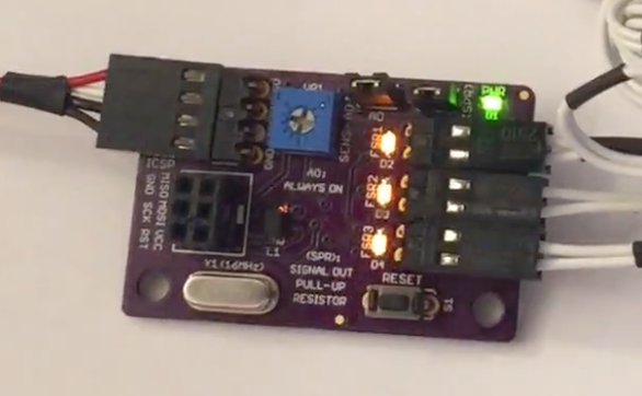
I wanted to share the FSR controller module for auto bed-leveling that I've designed to work specifically (but not exclusively) with the Duet.
Background
The initial inspiration for this mini-project came from JohnSL's excellent open-source project for this application.
At first I thought I'd experiment with the ready-made kit that's based on John's work and sold online commercially, but given the price-tag ($34.95 before shipping), I decided I'd rather make my own module with the exact specifications I'm looking for.
Both John's module and my own are designed to run 3 x FSRs (Force Sensitive Resistors) simultaneously, like the one shown below:

I got mine at RapidOnline, but they are readily available from numerous other suppliers, either with long or short leads.
The PCB dimensions of John's module and the one I made are also similar (though mine is slightly bigger), but that's where the similarities end as both the hardware and firmware are fundamentally different.
Design Considerations
I wanted to create a module that:
-
Can be seamlessly integrated with my Duet, but can also run in standalone mode (for testing and/or use in other, non-Duet machines).
-
Runs as fast and reliably as possible.
-
Has a minimal footprint.
-
Offers a convenient and easily accessible user interface, including onboard LEDs for indicating the initialization process and real-time sensor triggering.
-
Is able to automatically and quickly establish a baseline at startup against which to measure subsequent bed probes during the bed-leveling procedure.
-
Incorporates an adjustment mechanism for controlling the sensors' sensitivity level.
-
Can be reset manually to re-establish the measuring baseline.
-
Can be turned on (for bed-probing) or off (after the procedure is done).
-
Has an ICSP capability for bug fixes and/or future firmware updates.
-
Facilitates expandability to 6 x FSRs in case I'd like to go down that route at some point.
PCB
After some reading, head-scratching, and playing around with the PCB editor, I came up with the following design that covers all of the above:


Hardware Specs
-
5V Supply Voltage (I considered going with 3.3V like the Duet's logic, but in the end decided against it because I wanted the microcontroller to run at max speed)
-
Atmega328P-AU (smd version) @ 16MHz with an external crystal (for accurate timing)
-
ICSP header (for firmware updates/bug fixes)
-
Reset Button (for re-establishing the baseline for trigger measurements)
-
10K Trimmer (for manual sensitivity adjustment)
-
4 x LED indicators (1 x for power [green], and 3 x for each of the sensors [amber])
-
Signal Output - an Active-Low Open-Collector Combined signal for the 3 sensors (the signal is 5V, but is nevertheless compatible with the Duet interface via an onboard reversed diode).
-
An inductor/capacitor circuit for improved ADC readings of the sensors.
-
Control Input - for turning the module on/off via one of the Duet's I/O pins (see the Schematics pdf attached below for an example of how to turn the module on/off with the Duet).
-
Control Jumper - normally remains open, but can be closed to keep the module permanently on (for independent testing and/or use in other machines).
-
Pull-up resistor Jumper - normally remains open (as the Duet already has built-in pull-up resistors on its signal input pins), but can be closed for independent testing and/or use in other machines (essentially, closing this jumper converts the signal from open-collector type to a regular 5V/GND signal, but note that the signal is still Active-Low, i.e. 5V means none of the sensors is triggered, and GND means one or more are triggered)
-
Reversed Polarity Protection for the module's supply lines (by means of a P-channel mosfet).
-
The PCB itself was designed with the free version of Eagle and manufactured by OSHPark.
Firmware Specs
-
Firmware was written in Arduino-Style C using the free Arduino IDE.
-
I've used the 'nano' bootloader - rather than the conventional bootloader for the Atmega328P - because the smd version of this chip has more I/O pins and thus requires an appropriate bootloader to run properly.
-
When turned on, the module runs a quick calibration procedure (about 2 seconds), in which it samples each of the sensors and establishes a 'baseline' average against which to check sensor triggering at runtime (this is a crucial feature for preventing false readings from the sensors as there will always be some initial pressure present (from the build-plate's weight if nothing else).
-
The initialization (or calibration) process is visually indicated by all amber sensor LEDs flashing 4 times, after which the module enters runtime mode.
-
During runtime, the output signal is pulled low and the relevant amber LED lights up whenever one of the sensors is triggered (two or more sensors can be triggered simultaneously).
-
If sensor triggering appears to be too sensitive or not sensitive enough, the 10K trimmer can be adjusted and then the reset button clicked so as to re-run the calibration process.
Open Source Design Files
Important Disclaimer: I've been working with electronics for a long time, but I am nevertheless a hobbyist and not a professional hardware engineer of any kind. I can therefore give no guaranty about the content of these files, apart from the mere fact that I've built the module and tested it myself. Hence, should you choose to use any of the following materials (or their derivatives), you must also be willing to take full responsibility for doing so.
fsr controller - schematics (pdf)
fsr controller - parts (Excel .xlsx)
fsr controller - firmware (Arduino .ino)
fsr controller - schematics (Eagle .sch)
fsr controller - schematics (Eagle .brd)
See It Live!
Here's a link to a short demonstration of the module in action 
You'll notice that I click the 'reset' button on the module right at the beginning of the video - this is just to show the initial calibration process and isn't needed for normal operation.
Also, I haven't had a chance to install the module in my printer yet so there's still a lot of testing and potential firmware/hardware tweaking to be done, but given that many others have successfully implemented similar FSR architectures for bed-leveling (for example, see here), I'm hopeful this particular implementation would work out well too.
Should there be any interest, I'd be happy to report back on my progress with this, and of course, all comments/suggestions/corrections are always welcome 
Thanks for reading,
SnowCrash
