[[language]]
M913  Z30:30 ; Reduce current
M201 Z100; Reduce acceleration
M915 P1:2 S1 F0; Set stall detection threshold (you don't need this if you have it in config.g file)

G91
G1 S1 Z-210 F600 ; probe
G90

M201 Z1250 ; Restore acceleration
M913 Z50:50; Restore current

G92 Z0
G1 Z0.4 F3600; Stall triggers at -0.4mm, raise nozzle by 0,4mm.
G92 Z0

```Here is my code for z probe. The exact configuration would probably be different between each setup. You'll need to look for a setup that trigger the stall detection with the lowest impact force between the bed and the nozzle. Here is how I figured out mine:
First you need to lower your Z acceleration so stall detection won't trigger due to the force of z acceleration.
Then you need to figure out the lowest current that stall detection works reliably(M913). I found my motor moves reliably at 20% current, but stall detection works reliably at 30% current.
Then find the lowest stall detection thresh hold(M915). Mine is 1\. To avoid damage your printer always start with low values that would trigger the stall detection immediately, and increase the value until you can move the z axis.
You might also want to find the lowest speed as well to further reduce the impact force, but I just used F600.
Change any of the current, stall detection thresh hold and speed will probably effect the other 2\. You need to find a combination that works reliably and has the lowest impact force. To determine the impact force, I put a piece of print between the nozzle and the bed, and check the mark left by the nozzle after impact.
I don't have a spring under my bed, this might now work for you if you have a soft sprint under the bed.Best posts made by Shen
-
RE: Motor stall detection as Z probeposted in Tuning and tweaking
-
RE: 6th-order jerk-controlled motion planningposted in Firmware wishlist
@dc42
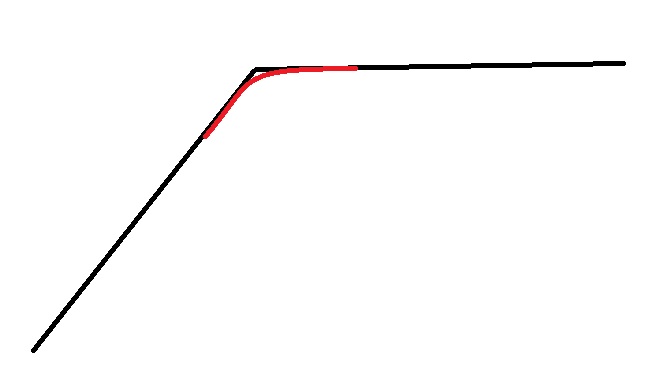
I think it might actually be better if you "deliberately change the motion path to be different from what the slicer specified in the GCode".

Instead of going along the black line as gcode instructs. It might be better to go along the red line. It will not only result in smoother motion, it might actually produce a better representation of the actual gcode path due to inertia of the print head. So basicly it's like a "pressure advance" for the XY motion. -
RE: 6th-order jerk-controlled motion planningposted in Firmware wishlist
@deckingman
The point that video of mater make is that with the S curve acceleration, moving mass comes to a stop without oscillation. In 3d printer this would result in less ringing.
When I say “the distance nozzle overshoot on a 90 degree corner is usually between 0.05 and 0.1mm”. That is just referring to this particular print. If you print the perimeter slowly or have very low jerk acceleration, you may not see the overshot, but the overshot still happens. The print head along any an axis cannot go from 5mm/s to 0mm/s instantly, it will overshot more or less, it might just not be visible for you. This is backed up by physics. Just like you compensate the elasticity of filament by pressure advance, you can also compensate for the elasticity of xy motion.
I don't know why you are so against the idea of an different different motion system. You want to see real world test results before you believe but every time this is brought up you just strongly oppose the idea, and even an experiment build. This might work well, or it might not bring any improvement, but how do we know without testing?