I recognize an RC is out, and should update to that. Error here may already be solved in future builds, but wanted to post anyways.
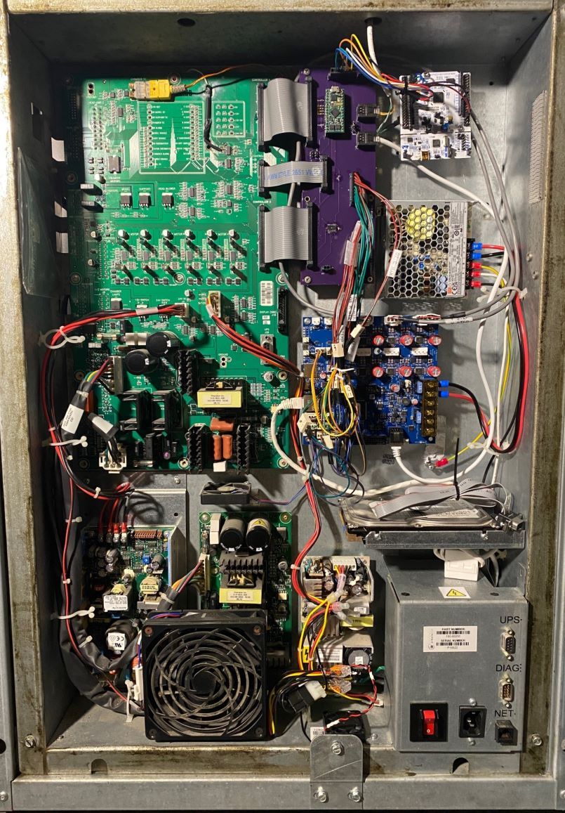
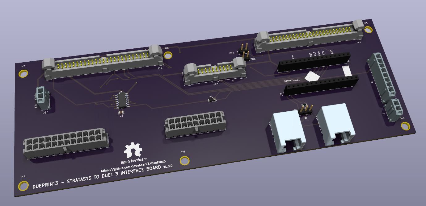
Commissioning a 'new' build - 6HC, Sammy-C21 as an expansion driving an external extruder motor. Walked up to the printer and witnessed the halt in real time.
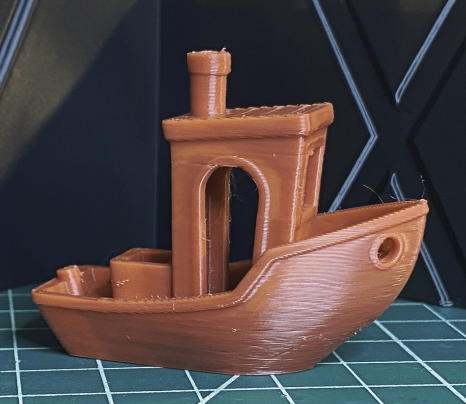
Paused in layer 86 of the attached print file: CFFFP_3DBenchy.gcode
Error: Movement halted because a step timing error occurred on drive 0 (code 2). Please reset the controller.
Error: Extra info=-9.765625e-4
M122
=== Diagnostics ===
RepRapFirmware for Duet 3 MB6HC version 3.6.0-beta.3+1 (2025-01-20 20:04:23) running on Duet 3 MB6HC v1.02b or later (standalone mode)
Board ID: 08DJM-9P63L-DJMSS-6J1D8-3SD6T-9VDZ8
Used output buffers: 1 of 40 (33 max)
=== RTOS ===
Static ram: 136892
Dynamic ram: 129160 of which 0 recycled
Never used RAM 76300, free system stack 130 words
Tasks: NETWORK(1,ready,33.1%,180) ETHERNET(5,nWait 7,0.1%,316) HEAT(3,nWait 6,0.0%,323) Move(4,invalid,0.5%,215) TMC(4,nWait 6,3.0%,341) CanReceiv(6,nWait 1,0.0%,769) CanSender(5,nWait 7,0.0%,327) CanClock(7,delaying,0.0%,341) MAIN(1,running,63.3%,440) IDLE(0,ready,0.0%,29) USBD(3,blocked,0.0%,149), total 100.0%
Owned mutexes:
=== Platform ===
Last reset 00:56:44 ago, cause: software
Last software reset at 2025-03-28 16:39, reason: User, Gcodes spinning, available RAM 76492, slot 2
Software reset code 0x0003 HFSR 0x00000000 CFSR 0x00000000 ICSR 0x00400000 BFAR 0x00000000 SP 0x00000000 Task MAIN Freestk 0 n/a
Error status: 0x00
MCU temperature: min 41.2, current 42.3, max 42.6
Supply voltage: min 47.5, current 48.0, max 48.3, under voltage events: 0, over voltage events: 0, power good: yes
12V rail voltage: min 12.1, current 12.3, max 12.5, under voltage events: 0
Heap OK, handles allocated/used 99/8, heap memory allocated/used/recyclable 2048/156/40, gc cycles 0
Events: 0 queued, 0 completed
Date/time: 2025-03-28 17:36:38
Slowest loop: 211.09ms; fastest: 0.07ms
USB interrupts 2
=== Storage ===
Free file entries: 19
SD card 0 detected, interface speed: 25.0MBytes/sec
SD card longest read time 2.8ms, write time 70.4ms, max retries 0
=== Move ===
Segments created 71, maxWait 485690ms, bed comp in use: none, height map offset 0.000, hiccups added 0/0 (0.00/53.45ms), max steps late 1, ebfmin 0.00, ebfmax 0.00
Pos req/act/dcf: 483.00/384/1.00 1953.00/2046/-1.00 11564.00/11564/-0.00
next step interrupt due in 214 ticks, disabled
Driver 0: standstill, SG min 0, mspos 648, reads 58364, writes 65 timeouts 3
Driver 1: standstill, SG min 0, mspos 24, reads 58364, writes 65 timeouts 3
Driver 2: standstill, SG min 0, mspos 696, reads 58364, writes 65 timeouts 3
Driver 3: standstill, SG min n/a, mspos 8, reads 58385, writes 44 timeouts 3
Driver 4: standstill, SG min n/a, mspos 8, reads 58385, writes 44 timeouts 3
Driver 5: standstill, SG min n/a, mspos 8, reads 58385, writes 44 timeouts 3
Phase step loop runtime (us): min=0, max=501, frequency (Hz): min=672, max=10416
=== DDARing 0 ===
Scheduled moves 55178, completed 55119, LaErrors 0, Underruns [0, 0, 0]
Segments left 1, axes/extruders owned 0x80000007, drives owned 0x80000007
Code queue is empty
=== DDARing 1 ===
Scheduled moves 0, completed 0, LaErrors 0, Underruns [0, 0, 0]
Segments left 0, axes/extruders owned 0x00000000, drives owned 0x00000000
Code queue is empty
=== Heat ===
Bed heaters -1 -1 -1 -1 -1 -1 -1 -1 -1 -1 -1 -1, chamber heaters 0 -1 -1 -1 -1 -1 -1 -1, ordering er=== GCodes ===
Movement locks held by null, null
HTTP is idle in state(s) 0
Telnet is idle in state(s) 0
File is doing "G1 X19.803 Y1.127 E0.01883" in state(s) 0
USB is idle in state(s) 0
Aux is idle in state(s) 0
Trigger is idle in state(s) 0
Queue is idle in state(s) 0
LCD is idle in state(s) 0
SBC is idle in state(s) 0
Daemon is idle in state(s) 0
Aux2 is idle in state(s) 0
Autopause is idle in state(s) 0
File2 is idle in state(s) 0
Queue2 is idle in state(s) 0
=== CAN ===
Messages queued 80102, received 27247, lost 0, ignored 0, errs 2684, boc 0
Longest wait 1ms for reply type 6018, peak Tx sync delay 46148, free buffers 50 (min 49), ts 16135/16132/0
Tx timeouts 0,0,2,0,0,0 last cancelled message type 30 dest 127
=== Network ===
Slowest loop: 204.57ms; fastest: 0.03ms
Responder states: MQTT(0) HTTP(0) HTTP(0) HTTP(0) HTTP(0) HTTP(0) HTTP(0) FTP(0) Telnet(0) Telnet(0)
HTTP sessions: 2 of 8
= Ethernet =
Interface state: active
Error counts: 0 0 0 1 0 0
Socket states: 6 2 2 2 2 0 0 0 0
=== WiFi ===
Interface state: disabled
Module is disabled
Failed messages: pending 0, notrdy 0, noresp 0
Socket states: 0 0 0 0 0 0 0 0
=== Multicast handler ===
Responder is inactive, messages received 0, responses 0
M122 B124
Diagnostics for board 124:
Duet SAMMYC21 firmware version 3.6.0-beta.3+1 (2025-01-20 20:01:57)
Bootloader ID: not available
All averaging filters OK
Never used RAM 9444, free system stack 71 words
Tasks: Move(3,nWait 7,0.2%,86) HEAT(2,nWait 6,0.1%,128) CanAsync(5,nWait 4,0.0%,66) CanRecv(3,nWait 1,0.1%,70) CanClock(5,nWait 1,0.0%,58) MAIN(1,running,98.3%,436) IDLE(0,ready,0.0%,26) AIN(2,delaying,1.3%,120), total 100.0%
Owned mutexes:
Last reset 01:11:39 ago, cause: software
Last software reset data not available
Moves scheduled 50341, hiccups 697 (53.45/53.45ms), segs 23, step errors 0 (types 0x0), maxLate 0 maxPrep 272, ebfmin 0.00 max 0.00
Peak sync jitter 3/8, peak Rx sync delay 293, resyncs 0/0, no timer interrupt scheduled, next step interrupt due in 3582982220 ticks, disabled
MCU temperature: min 39.0C, current 39.2C, max 39.8C
Driver 0: pos 9953144, 3230.8 steps/mm
Last sensors broadcast 0x00000000 found 0 6 ticks ago, 0 ordering errs, loop time 0
CAN messages queued 34423, send timeouts 0, received 87925, lost 0, ignored 0, errs 0, boc 0, free buffers 18, min 18, error reg 0
dup 0, oos 0/0/0/0, bm 0, wbm 0, rxMotionDelay 466, adv 35536/47502
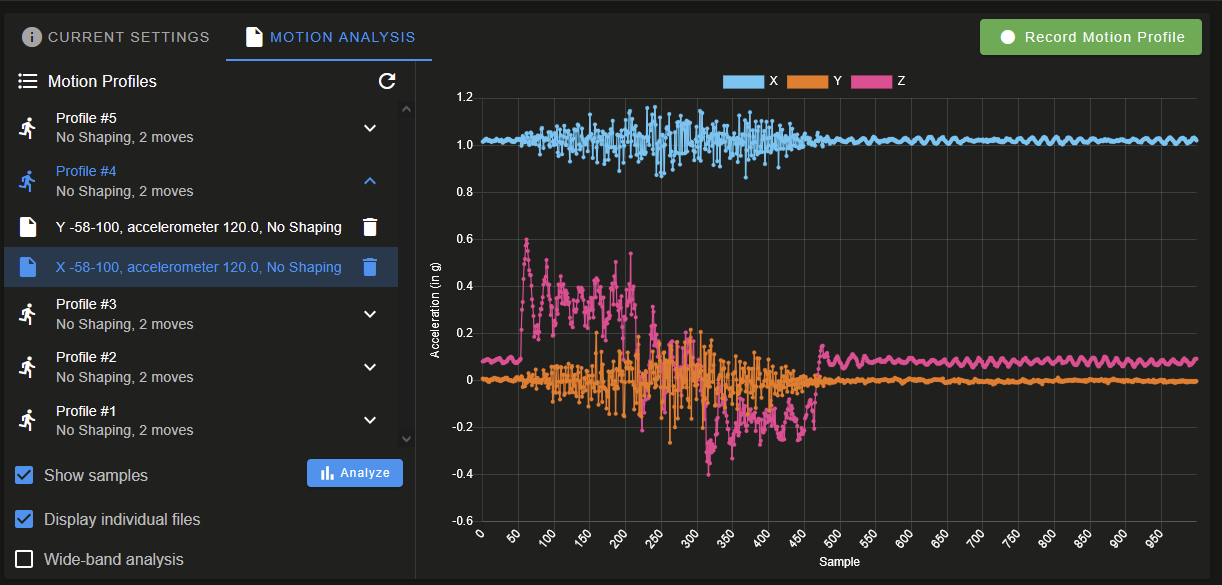
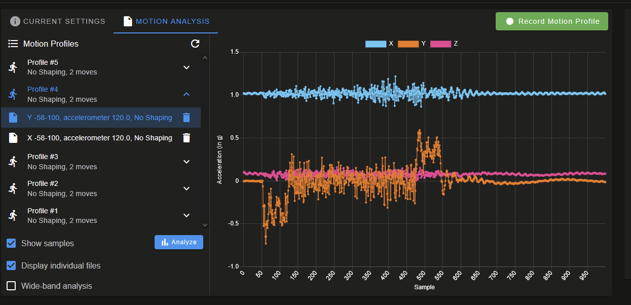
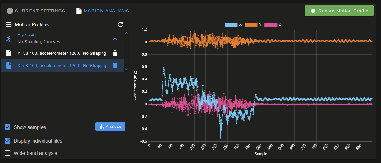
Accelerometer: none
Inductive sensor: not found
I2C bus errors 0, naks 0, contentions 0, other errors 0
config.g
; Default config.g template for DuetPi
; Replace this with a proper configuration file (e.g from https://configtool.reprapfirmware.org)
; Display initial welcome message
;M291 P"Please go to <a href=""https://www.duet3d.com/StartHere"" target=""_blank"">this</a> page for further instructions on how to set it up." R"Welcome to your new Duet 3!" S1 T0
; Enable network
if {network.interfaces[0].type = "ethernet"}
M552 P192.168.100.56 S1
else
M552 I1 S1
M552 I1 S1 ; enable wifi
G4 S2 ;wait for expansion boards to start
; Drives
M569 P0 S1 ;physical drive 0 goes backwards, X-Axis
M569 P1 S0 ;physical drive 1 goes forwards, Y-Axis
M569 P2 S1 ;physical drive 2 goes forwards, Z-Axis
M569 P124.0 S0 T0:0:0:0 ;external driver on sammy
M584 X0 Y1 Z2 E124.0 ;set drive mapping
M350 X16 Y16 Z16 E16 I1 ;configure microstepping with interpolation
M92 X53.33 Y134 Z629.864 E3230.77 ;set steps per mm was 1011.99 then 1594.6, then 642.61
M566 X600 Y600 Z60 E3000 ;set jerk
M203 X30000 Y18000 Z1200 E1800.00 ;set max speeds (mm/min)
M201 X2500 Y3500 Z2000 E3000 ;set max accelerations (mm/s^2)
M201.1 X750 Y750 Z2000 E3000 ;max special acceleration move (homing)
M906 X1800 Y2600 Z2600 I30 ;set motor currents (mA) and motor idle percent
M84 S30 ;set idle timeout
M208 X-138.3 Y-137.5 Z-2 S1 ;set axis minima
M208 X160.4 Y178.5 Z325.116 S0 ;set axis maxima
; Toggle nozzle min - -163.2 , 206 max
; X EOT toggles at 181.2
; Y EOT at 182.4
;purge bucket near middle - x162.5, y155.5
;z probe left toggle -136.5
;z probe right toggle 197.5
;from build plate center, model (right) offset x=+20.8 (too far right), support is +40.8
;from build plate center, Y offset = -23 (too far forward)
;Z bottom (EOT) 325.1
;Endstops
M574 X1 S1 P"!io0.in" ; X home limit (low side)
M574 Y1 S1 P"!io1.in" ; Y home limit (low side, toward front of printer
M574 Z2 S1 P"!io6.in" ; assign Z EOT to x endstop on high side
; Z-Probe
M558 P5 H5 F1200:200 T5000 C"!io2.in" ; Z probe, set dive height, probe speed and travel speed
;G31 P1000 X-46 Y-74 Z0.896
G31 P1000 X-24 Y-73 Z1.365
;G31 P1000 X24 Y96 Z0.896 ; set Z probe trigger value, offset and trigger height
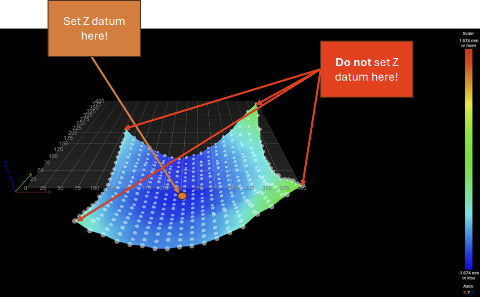
M557 X-135:135 Y-135:65 P5:5 ; define mesh grid. The whole bead cannot be probed due to the position of the probe.
; Head Blower Fan
M950 P0 C"!out4"
M42 P0 S0 ; enable blower
; Extruder Motor Enable
M950 P1 C"!out5"
M42 P1 S0
; Touch Power Enable
M950 P2 C"!out6"
M42 P2 S0
; Door Enable
M950 P3 C"io6.out"
M42 P3 S0
; LED Lights Enable
M950 P4 C"io2.out"
M42 P4 S1 ;S1 to turn on!
; Gecko Reset
M950 P5 C"io0.out"
M42 P5 S0
; Thermocouples
M308 S0 A"Chamber Test" P"temp0" Y"linear-analog" F0 B-42 C113
M308 S1 A"Model Test" P"temp1" Y"linear-analog" F0 B12.5 C328
M308 S2 A"Support Test" P"temp2" Y"linear-analog" F0 B12.5 C328
; Heaters
M140 H-1 ;Disable bed heater
M950 H0 C"!out7" T0 ; chamber, sensor 0
M141 H0 ; map chamber to heater 0
M143 H0 S85 ; set temperature limit for heater 0 to 85C
M570 H0 P30 T10 ; Increase fault delay to 30s, decrease temperature fault to 10c
M950 H1 C"!out8" T1 ; model, sensor 1
M143 H1 S320
M570 H1 P30 ; set fault time delay to 30s for heater 1
M950 H2 C"!out9" T2 ; support, sensor 2
M143 H2 S320 ; set temperature limit for heater 1 to 320C
M570 H2 P30 ; set fault time delay to 30s for heater 2
; Tools
M563 P0 S"Model" D0 H1 ; define tool 0
G10 P0 X0 Y0 Z0 ; set tool 0 axis offsets
G10 P0 R0 S0 ; set initial tool 0 active and standby temperatures
M563 P1 S"Support" D0 H2 ; define tool 1
G10 P1 X-20 Y0 Z0 ; set tool 1 axis offsets
G10 P1 R0 S0 ; set initial tool 1 active and standby temperatures
; Gecko Error In
M950 J0 C"124.pa04" ;gecko error in
; Head Thermostat Status
M950 J1 C"124.pa05"
; Door In
M950 J2 C"124.pa06"
; Print Head Support Toggle
M950 J3 C"124.pa07"
; Print Head Model Toggle
M950 J4 C"124.pa19"
; X-axis EOT
M950 J5 C"!io3.in"
; Y-axis EOT
M950 J6 C"!io4.in"
; Z-axis Home
M950 J7 C"!io5.in"
; Z-axis EOT
;M950 J8 C"!io6.in"
; Print Head Temp Alarm
M950 J9 C"!io7.in"
; Chamber Temp Alarm
M950 J10 C"!io8.in"
;M581 Tx P5:6:7:8
M501 ;config g
M302 S200 R200
M98 P"globals.g"

 !
!
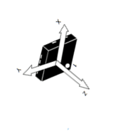
 ). I can try and find where the orientation is defined later.