@jay_s_uk Wow I seriously have read over that 10 times I think. sorry for the unnessecary question
Thanks all!
Best posts made by SanderLPFRG
-
RE: On-device start gcode handlingposted in Gcode meta commands
-
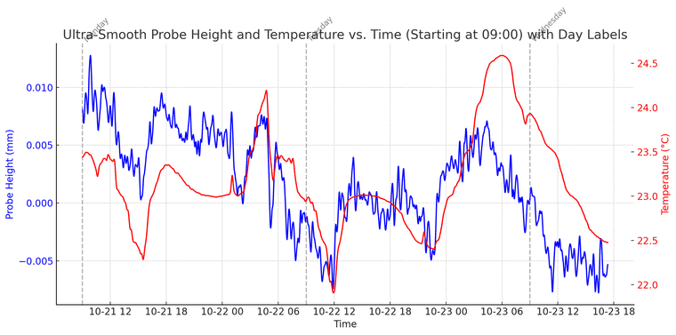
RE: longterm probe reliability testingposted in Gcode meta commands
@Notepad works really well, thanks!
Got good results too, and plotted them in graphs! which shows a fun correlation of the temperature drift of our probe!
Thanks for the script! Appreciate it
-
RE: How do I use the filament sensor as a trigger for autoloading??posted in Filament Monitor
@OwenD I did exactly that yesterday late afternoon. It is working now.
; Custom buttons
M950 J1 C"^io2.in"      ; define logical input for E1 filamentsensor
M581 P1 T2 S0 R2        ; define trigger for filament auto load (trigger2.g)
M581 P1 T4 S1 R1        ; define trigger for filament runout (trigger4.g)
Thank you very much both!
-
RE: Other analog Scanning Z Probes?posted in Firmware wishlist
@SanderLPFRG Got it working, version mismatch.
-
RE: Trying to fix my dual markforged (HAQ-XY) kinematicsposted in Tuning and tweaking
@gloomyandy said in Trying to fix my dual markforged (HAQ-XY) kinematics:
at it is probably not a good thing
Ill redesign the belt tensioning mechanism and the belt mounting, when measuring it indeed looks to be too loose
WIll see what this does -
RE: M291 S4+ commands not working on RRF 3.5beta2posted in Gcode meta commands
@chrishamm It works!!
It both updated correctly, and now the M291 functions correctly.
Massive thanks Chris and Tony.I'll now work on trying to understand how I can use the input to trigger Gcode commands
-
Home aditional V/W axis individually with probeposted in MultiAxis Printing
Hi all,
We have made a 3D printer with 2 micro-Z printhead axes (V and W), which move the IDEX printheads up and down 14mm to level 2 different tool types and automatically adjust/calibrate the printhead Z-offset.
We first got this system working with a microswitch type probe, which we, in a macro, temporarily reconfigured as an endstop for axis V/W, which we then "homed" towards the printed until triggered. When done for both tools, this calibrated the Z-offset automatically.
Now, however, we moved over to a loadcell probe (analog readout via configuring as scanning Z-probe, amplified and filtered with custom CAN-communicated PCB) which we cannot configure as an endstop to home towards.
My question is;
Is it possible to do a G30 S-1 probe (just probe and stop) with a probe number defined (K0/K1), but move axis V or W instead of the Z-axisnote;
running 3.6.0 beta-2 -
RE: move outside of machine limits with G2 move, in tool 2posted in Beta Firmware
@T3P3Tony Hey Tony,
We found the issue to be regarding the V axis being too low.
Why it triggered only with G2 enabled gcodes remains a question still, but since we adapted the starting codes to account for the V being out of bounds we have not had the issue.
Maybe an improvement is to add the relevant axis number to the errorcode for future firmware?
-
RE: Cannot use M291 input as variable in loopposted in Gcode meta commands
@OwenD Damn, this did the trick. Thank you so much owen! also thanks @chrishamm
-
RE: Home aditional V/W axis individually with probeposted in MultiAxis Printing
@gloomyandy G38.2 in the end worked!!
You can move an axes until the specified probe is triggered. Works like a charm.
G38.2 K0 V-14 G38.2 K1 W-14 -
RE: longterm probe reliability testingposted in Gcode meta commands
My goal is to test a shitload of probes, and see how much it starts to deviate after thousands. Your script might actually work, let me test
-
RE: Mesh compensation which accounts for G10 X&Y tool offsetsposted in Gcode meta commands
@fcwilt
Yes, in short.The G-code is printing between X-50 and X50. When I measure the adaptive mesh over this area (the middle of the bed) and then print in mirror mode, the firmware applies the mesh data from X-50 to X50, even though the print is shifted to an offset region (e.g., X-150 to X-50 with a 100mm offset).
To fix this, I trick RRF into measuring the offset area (X-150 to X-50) while it believes it's probing around X0. This way, when printing, it applies the heightmap it thinks is from X0, but it's actually from the offset area where the print will take place.