@jay_s_uk Wow I seriously have read over that 10 times I think. sorry for the unnessecary question
Thanks all!
Best posts made by SanderLPFRG
-
RE: On-device start gcode handlingposted in Gcode meta commands
-
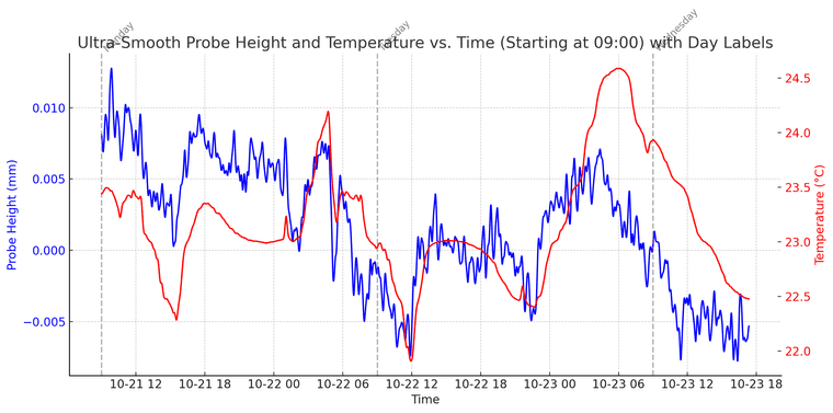
RE: longterm probe reliability testingposted in Gcode meta commands
@Notepad works really well, thanks!
Got good results too, and plotted them in graphs! which shows a fun correlation of the temperature drift of our probe!
Thanks for the script! Appreciate it
-
RE: How do I use the filament sensor as a trigger for autoloading??posted in Filament Monitor
@OwenD I did exactly that yesterday late afternoon. It is working now.
; Custom buttons
M950 J1 C"^io2.in"      ; define logical input for E1 filamentsensor
M581 P1 T2 S0 R2        ; define trigger for filament auto load (trigger2.g)
M581 P1 T4 S1 R1        ; define trigger for filament runout (trigger4.g)
Thank you very much both!
-
RE: Other analog Scanning Z Probes?posted in Firmware wishlist
@SanderLPFRG Got it working, version mismatch.
-
RE: Trying to fix my dual markforged (HAQ-XY) kinematicsposted in Tuning and tweaking
@gloomyandy said in Trying to fix my dual markforged (HAQ-XY) kinematics:
at it is probably not a good thing
Ill redesign the belt tensioning mechanism and the belt mounting, when measuring it indeed looks to be too loose
WIll see what this does -
RE: M291 S4+ commands not working on RRF 3.5beta2posted in Gcode meta commands
@chrishamm It works!!
It both updated correctly, and now the M291 functions correctly.
Massive thanks Chris and Tony.I'll now work on trying to understand how I can use the input to trigger Gcode commands
-
Home aditional V/W axis individually with probeposted in MultiAxis Printing
Hi all,
We have made a 3D printer with 2 micro-Z printhead axes (V and W), which move the IDEX printheads up and down 14mm to level 2 different tool types and automatically adjust/calibrate the printhead Z-offset.
We first got this system working with a microswitch type probe, which we, in a macro, temporarily reconfigured as an endstop for axis V/W, which we then "homed" towards the printed until triggered. When done for both tools, this calibrated the Z-offset automatically.
Now, however, we moved over to a loadcell probe (analog readout via configuring as scanning Z-probe, amplified and filtered with custom CAN-communicated PCB) which we cannot configure as an endstop to home towards.
My question is;
Is it possible to do a G30 S-1 probe (just probe and stop) with a probe number defined (K0/K1), but move axis V or W instead of the Z-axisnote;
running 3.6.0 beta-2 -
RE: move outside of machine limits with G2 move, in tool 2posted in Beta Firmware
@T3P3Tony Hey Tony,
We found the issue to be regarding the V axis being too low.
Why it triggered only with G2 enabled gcodes remains a question still, but since we adapted the starting codes to account for the V being out of bounds we have not had the issue.
Maybe an improvement is to add the relevant axis number to the errorcode for future firmware?
-
RE: Cannot use M291 input as variable in loopposted in Gcode meta commands
@OwenD Damn, this did the trick. Thank you so much owen! also thanks @chrishamm
Latest posts made by SanderLPFRG
-
RE: Mesh compensation which accounts for G10 X&Y tool offsetsposted in Gcode meta commands
@dwuk3d
I do think the Macro would not be able to be run during printing.But, if running on SBC-mode, you might be able to write a program to process the mesh?? it should be able to call the ".csv" to use it and pre-process it.
might be interesting to call in on some multi-axes printing guys as well!
-
RE: Mesh compensation which accounts for G10 X&Y tool offsetsposted in Gcode meta commands
@fcwilt It does work, but ofcourse it assumes the Right side is mirrored to the Left side
my duplication start gcode, if anyone wants to use it;
; Setup variables var lefttemp = 0 var righttemp = 0 var bed = 0 var printxmin = 0 var printxmax = 600 var printymin = 0 var printymax = 500 var sizex = 50 var pointsx = 3 var sizey = 50 var pointsy = 3 var purgelength = 15 var initialtool = 0 var leftused = "false" var rightused = "false" var leftfilament = "none" var rightfilament = "none" var leftnozzlesize = 0 var rightnozzlesize = 0 var dualprintingoffset = 167.5 ; Define variables ; Temperature variables set var.lefttemp = param.A ; Extruder temperature set var.righttemp = param.B ; Extruder temperature set var.bed = param.C ; Bed temperature ; Print variables set var.printxmin = param.D ; Left boundry set var.printxmax = param.E ; Right boundry set var.printymin = param.F ; Front boundry set var.printymax = param.H ; Back boundry set var.sizex = {var.printxmax - var.printxmin} set var.sizey = {var.printymax - var.printymin} ; Machine variables set var.initialtool = param.I ; initial tool set var.leftused = param.J ; is right tool used yes/no set var.rightused = param.K ; is right tool used yes/no set var.leftfilament = param.L ; loaded filament type left set var.rightfilament = param.O ; loaded filament type right set var.leftnozzlesize = param.Q ; nozzle diameter left set var.rightnozzlesize = param.R ; nozzle diameter right ; set probing amount for Y if var.sizex <= 150 ; if sizeX is less than 150mm, set probing X amount to 3 set var.pointsx = 3 elif var.sizex <= 350 ; if sizeX is between 150mm and 350mm, set probing X amount to 5 set var.pointsx = 5 elif var.sizex <= 450 ; if sizeX is between 350mm and 450mm, set probing X amount to 7 set var.pointsx = 7 else ; if sizeX is between 450mm and max, set probing X amount to 9 set var.pointsx = 9 ;endif ; set probing amount for Y if var.sizex <= 100 ; if sizeX is less than 100mm, set probing X amount to 3 set var.pointsx = 3 elif var.sizex <= 300 ; if sizeX is between 100mm and 300mm, set probing X amount to 5 set var.pointsx = 5 elif var.sizex <= 400 ; if sizeX is between 300mm and 400mm, set probing X amount to 7 set var.pointsx = 7 else ; if sizeX is between 400mm and max, set probing X amount to 9 set var.pointsx = 9 ;endif ; General settings; G90 ; set absolute coordinates T0 ; Heat up for probing M104 T0 S150 ; set extruder temp for bed leveling M104 T1 S150 ; set extruder temp for bed leveling M140 P0 S{var.bed} ; set bed temperature zone 2 M140 P1 S{var.bed} ; set bed temperature zone 1M109 T0 S150 ; wait for hotend probing temp M109 T1 S150 ; set extruder temp for bed leveling M190 P0 S{var.bed} ; wait for bed temperature zone 1 M190 P1 S{var.bed} ; wait for bed temperature zone 1; Prepare for automatic calibration M302 S140 ; lower cold extrusion limit to 160C G1 E-2 F2400 ; cold retraction M302 S170 ; restore cold extrusion limit G32 ; home printer ; Start mesh offsetting G1 X0 Y0 F6000 Z10 G91 G1 X{-var.dualprintingoffset} ; move X to offset G92 X0; set position back to original ; Actual position is now 150mm offset compared to assumed position M557 X{var.printxmin, var.printxmax} Y{var.printymin, var.printymax} P{var.pointsx, var.pointsy} ; Define adaptive mesh area around X=0 G29 ; Measure bed. ;G30 Z-9999 ; Machine assumes this is around X=0 position, while it is actually measuring offset area G1 X0 Y0 F6000 Z10 G92 X{-var.dualprintingoffset}; set position back to original ; Heat up for printing G90 ; absolute coordinates G1 X-360 U360 Y-240 Z15 F6000; move to park position T2 M109 S{var.lefttemp} -
RE: Mesh compensation which accounts for G10 X&Y tool offsetsposted in Gcode meta commands
@dwuk3d The micro-Z compensation is above my knowledge-grade, but the main difficulty remains that there needs to be a centralized program that knows;
- The XYU coordinates of all printing moves
- The offset amount compared to known slicer movement axis to the new positions of toolheads
- The heightmap of the used area of the printed
Then it would need to look up all X and Y coordinates of the print, offset them to generate a T (Offseted X to T1) and U (Offseted X to T2) coordinage, and then create a V movement parameter for the T/Y coordinate, and then a W movement for the U/U coordinate.
BUT, this assumes you do not want to use a taper height
-
RE: Mesh compensation which accounts for G10 X&Y tool offsetsposted in Gcode meta commands
@fcwilt
Yes, in short.The G-code is printing between X-50 and X50. When I measure the adaptive mesh over this area (the middle of the bed) and then print in mirror mode, the firmware applies the mesh data from X-50 to X50, even though the print is shifted to an offset region (e.g., X-150 to X-50 with a 100mm offset).
To fix this, I trick RRF into measuring the offset area (X-150 to X-50) while it believes it's probing around X0. This way, when printing, it applies the heightmap it thinks is from X0, but it's actually from the offset area where the print will take place.
-
RE: Mesh compensation which accounts for G10 X&Y tool offsetsposted in Gcode meta commands
@fcwilt Correct,
See the code snippet I sent above; it automatically measures a mesh that is offset by the X value of duplication.
It gives the same result as manually offsetting the CSV file.
This indeed gives a good compensation for left half, and the right half follows, which is not ideal but works better than no compensation.
Ideally, you could also do the compensation with user-defined axis ( we have a microZ which moves the X and U printhead up and down) which could be used for mesh compensation like @dwuk3d also mentioned. I guess that requires a huge overhaul of how printing with 2 printheads works in Duet tho.. We could also integrate it into a slicer (post-processing) to send a G1 X, U, Y, Z, V, and W position. But then the slicer also needs to know the mesh heightmap
-
RE: Mesh compensation which accounts for G10 X&Y tool offsetsposted in Gcode meta commands
Mesh compensation cannot work for two printheads at the same time - it could adjust the bed for one or the other, but not both.
The video suggests it is applying the entire heightmap twice, once to the left half and again to right half of the bed.
Which, in a way, makes sense since mirroring essentially splits the bed into two equal parts.
However it does no good at all as the heightmap doesn't match either half of the bed.Theoretically it should not, but yet it does actively apply a mesh. It indeed looks like it is applying the same heatmap twice, but in any case it would be better to keep the mesh origin in the middle, and only use the left side. The physical bed does not move.
In our case it is definitely not ideal, nor perfectly mirrored along X=0, but it definitely is significantly better to compensate more than nothing.
I currently got it working with this code;
G1 X0 Y0 F6000 Z10 ; move to controlled position while G90 G91; set to relative G1 X{-var.dualprintingoffset} ; move X to offset position G92 X0; Force new position to X=0 ; Actual position is now 150mm offset compared to assumed position M557 X{var.printxmin, var.printxmax} Y{var.printymin, var.printymax} P{var.pointsx, var.pointsy} ; Define adaptive mesh area around duplication position G29 ; Measure bed. ; Machine assumes this is around X=0 position, while it is actually measuring offset area G1 X0 Y0 F6000 Z10 ; move back to controlled position G92 X{-var.dualprintingoffset}; set position back to original X=0 -
RE: Mesh compensation which accounts for G10 X&Y tool offsetsposted in Gcode meta commands
@fcwilt Here are some videos;
Height map was set at 50 , 0 , 50 to make it really clear for the video
Movement Left printhead; https://photos.app.goo.gl/FJuenGCBoZD6ia7j6
Movement Right printhead; https://photos.app.goo.gl/8H9C4EzgjiuiZuvc7
Movement Mirrored; https://photos.app.goo.gl/6M6dbW1AvHj1x8A36(uploaded like this because of limited upload size)
-
RE: Mesh compensation which accounts for G10 X&Y tool offsetsposted in Gcode meta commands
@fcwilt I managed to make one as well
Testing I just did;
Height map of +5 , 0, +5, so a V shape loaded- When selecting and jogging with Left toolhead, it follows the path correctly, and changes the Z-compensation direction perfectly at the middle of the whole bed
- When selecting and jogging with Right toolhead, it follows the path correctly, and changes the Z-compensation direction perfectly at the middle of the whole bed
- When selecting the mirror tool (see config below), it still applies a V-shaped bed correctly, but it offsets the mesh as well, so then it is mirroring at the quarter of the whole bed
config;
; Tool Left
M563 P0 S"Left" D0 H2 X0 F0     ; define tool 0
G10 P0 X0 Y0 Z0                 ; set tool 0 axis offsets
G10 P0 R0 S0                    ; set initial tool 0 active and standby temperatures to 0C

; Tool Right
M563 P1 S"Right" D1 H3 X3 F1    ; define tool 1
G10 P1 U0 Y0 Z0.15       ; set tool 1 axis offsets
G10 P1 R0 S0                    ; set initial tool 1 active and standby temperatures to 0C

; Tool Mirror
M563 P2 S"Mirror" D0:1 H2:3 X0:3 F0:1     ; tool 2 uses both extruders, hot end heaters and fans, and maps X to both X and U
G10 P2 X150 Y0 U-150 S0 R0                      ; set tool offsets and temperatures
M567 P2 E1:1                                    ; set mix ratio 100% on both extruders
Expected behavior would be to compensate and move in 1 direction only, when mirrored mode is selected (when moving from outside to the middle of the bed
-
RE: Mesh compensation which accounts for G10 X&Y tool offsetsposted in Gcode meta commands
@fcwilt said in Mesh compensation which accounts for G10 X&Y tool offsets:
ed having a Z range of 0mm to 5mm it was easy to see the mesh compensation a
Smart testing Idea,
Can you share the simple CSV you made?? Maybe our issue lies with having both X and U mapped to the X movements? I wonder if it then follows with the X or the U axis?
-
RE: Mesh compensation which accounts for G10 X&Y tool offsetsposted in Gcode meta commands
@fcwilt So If I understand correctly;
If I have a mesh present at X-200 to X-100 and print at X-50 to X50 with a G10 offset of -150, will it still print with the correct compensation?