@Phaedrux said in Heater Fault - Temperature raising slowly:
What command did you use to tune the extruder heater?
M303 H2 S230
Are the ambient conditions different now than from the tuning?
No.
@Phaedrux said in Heater Fault - Temperature raising slowly:
What command did you use to tune the extruder heater?
M303 H2 S230
Are the ambient conditions different now than from the tuning?
No.
Hello,
I am using a pellet extruder (https://mahor.xyz/) with roto toolboard and Duet3 6HC mainboard. Running FW 3.5.2. I have already performed autotuning using M303 and have updated the M307 in config.g
; Sensors
M308 S2 P"22.temp1" Y"pt1000" A"Tool3_Temp";  T4606017 B5848 C5.548428e-8 R4700 H0 L0 ; configure sensor #2 - Pellet extruder

; Heaters
M950 H2 C"22.out0" T2 ; create heater #2
M143 H2 P0 T1 C0 S300 A0 ; configure heater monitor #0 for heater #2
M307 H2 R3.732 K0.814:0.000 D3.14 E1.35 S1.00 B0 V22.0
;M307 H2 R2.43 D5.5 E1.35 K0.56 B0 ; configure model of heater #2
M570 H2 P20 T20 ; An anomaly on heater 2 must persist for 20 seconds, and must be greater or less than 20C from the setpoint, to raise a heater fault.
I get the following error during heating. Also tried increasing limits in M570, but still gives me an error.
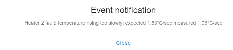
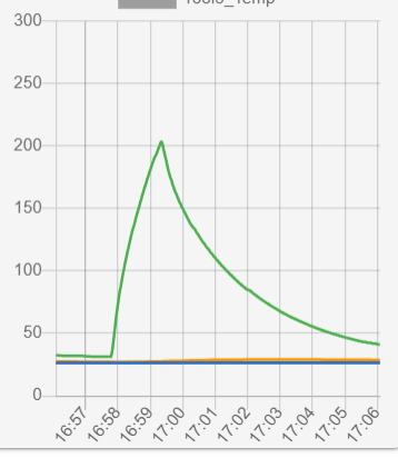
How do I resolve this error?
Hello,
I am writing a program where I want to use variables as X and Y coordinates in a G1 move command.
var loopCounter = 0

; values are machine position from camera calibration
var t1X = 0
var t1Y = 0

G1 X{t1X} Y{t1Y} F1000; Move to camera calib position
G1 X{t1X-7.95} Y{t1Y-47.9} F1000; move to secondary position
I am getting error "unknown value 't1X"
What is the correct way to declare and set a variable to a decimal number?
@droftarts Thank you. Also, When I try to save the machine Z position at which the Z probe was triggered as the Z offset using G10, nothing happens
G10 P1 X{-move.axes[2].machinePosition}
What is the correct way to update the Z offset after M585? I have noticed the Z offset is not retained after the tool change.
@droftarts Thanks for pointing me to M558 A and S parameters
in my config.g, I have defined a Z probe as follows:
; Z Probe
M558 K0 P5 C"!io3.in" A5 S-1 F130:100 T100 ; Z-probe tool setter connected to io3.in pin, Type 5 (switch- NC), Probe 5 times and average the results
I move the nozzle about 5 mm above the tool setter and issue the following command in DWC
M585 Z5 P0 S1 F100
The probing just happens once and stops. I see the Z offset value automatically updated (Current Z position under axis name in DWC changes), However, probing is not happening 5 times as defined in M558. Any suggestions as to why this may be happening?
Hello,
I am building a custom multi-tool tool changer system and now working on the Z calibration process. I am using a precision tool setter-type switch where each tool will come down touch the tool setter and register the machine Z coordinate. I am thinking of the following sequence of actions:
rough attempt at trying to code this
; calibrateZ.g

T1; Select and load tool 1
M109 P1 S215; Set temp (can also use M568??)
M116 P1; Wait to reach temp

G1 X0.0 Y0.0 F1000; move to HRP set to above Z tool setter sensor. X and Y offsets for tool stored in tpre#.g using G10 P1 Xnnn Ynnn Z0.0

var zPos = {}; 5 element array - not sure how to define this
for(i=1;i<=5;i++)
{
G30 S-1;
zPos(i) = move.axes[2].machinePosition;
G1 Zxx F100; relative move up
}

; compute the average of zPos array
; compute std dev of zPos array

if (stddev(zPos) > threshold)
alert user
stop
else
;set Z offset G10 P1 Z{avg(zPos)} - need to check sign

M109 P1 S0; Set temp (can also use M568??)
T-1 P1; unload tool 1

; repeat for remaining tools
Questions:
@droftarts Tested this and works as expected. Just changed the 2K resistor to a 2.7K resistor to limit the overall current below 10mA. Thanks
@droftarts Ah! This makes sense. Will give this a try. Thanks
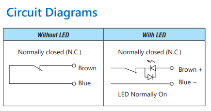
@droftarts Ian, I tried adding the 330 ohm resistor between io3.in and GND - this causes the original 19.8V to drop to 3.2 V when switch is pressed (open); however in its closed (default) condition the voltage just drops from 1.9V to 1.8V. So now I am getting voltages in the range 1.8V to 3.2V and the lower voltage is still higher than the threshold for input pin.
LED does light up on the switch when powered (default state is NC) and goes off when pressed (open) as it should.
Any suggestions on how to further reduce the lower voltage so that it’s below the threshold? A circuit diagram would be helpful.
@Phaedrux FW and DWC both at 3.5.2
@oliof Thank you for the suggestion but there is no print head movement in this test. I am pressing the switch manually and actually holding it pressed for a few seconds. Still no change in Z probe reading shown in DWC and also in Object model.
@Phaedrux Understood, but the issue seems to be the Z probe not changing value in DWC even with manual triggering. The documentation says to expect 0 when not triggered and 1000 when triggered.
Checking the voltages using a multi-meter, I can clearly see the change from 1.9V to 19.8V with manually pressing the Z probe/switch.
Any suggestions on what is going on and why the Z probe value is not changing?
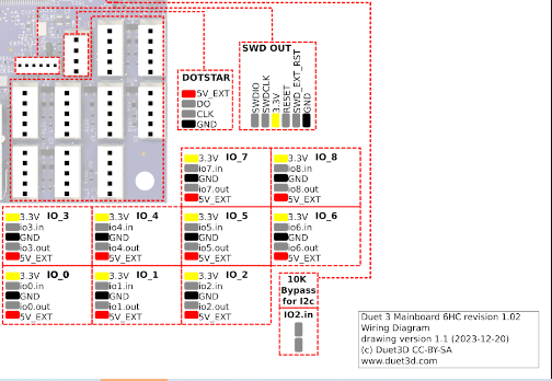
@dc42 Thanks for the info. I have created a circuit as below. The brown and blue wires represent the two wires from the switch/sensor.
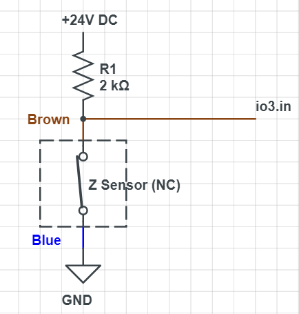
I have tested the voltage between io3.in and GND using a multimeter. When the Switch is not pressed, the reading is about 1.8V, and when the switch is pressed, the reading changes to 19.8V
I have configured a Z probe in config.g as follows:
; Z Probe
M558 K0 P5 C"!io3.in" ; Z-probe tool setter connected to io3.in pin
However, when the value of the Z probe in DWC doesn't seem to change. It just stays at 0. Even manually pressing the switch to trigger it does nothing, but I can see the voltages change in the multimeter
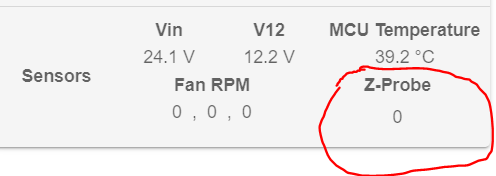
Any suggestions as to why the Z probe value in DWC is not changing?
I plan to use M585 to determine Z height during probing.
@jay_s_uk @droftarts @dc42 any suggestions?
There is an LED indicator on the sensor and a 10mA limit so the LED doesn't get damaged when connected to 24V. I have soldered a 2K ohm resistor to limit the current. Simple testing by directly connecting the brown wire to +24V and black to GND works fine. The sensor is NC, and pressing the plunger breaks the circuit.
I was thinking of connecting the brown (+) to iox.in and black (-) to the GND in the IO port of Duet3 6HC and enabling pull-up resistor. Still need to connect it to 24V to power it and I am not sure how to do this with only two wires.
@jay_s_uk One with LED. Both are two wires though. There is no separate "signal" wire that can be wired to iox.in; Hence was a little confused.
Hello,
I want to use a high-precision tool setter limit switch (https://www.automationdirect.com/adc/shopping/catalog/sensors_-z-_encoders/limit_switches/plunger_actuator/p11ddb-duld) as a Z probe in a multi-tool tool changer machine. Each tool will come down and touch this sensor as part of Z calibration.
The sensor only has two wires and was wondering what would be the best way to wire this.
Datasheet: https://cdn.automationdirect.com/static/specs/lshighprectoolsetls.pdf
Since there is no "signal" input to wire into the IO port on Duet3 mainboard, What would be the best way to wire and configure this 2-wire sensor as a Z probe?
Hello,
What is the best source to buy additional Molex microfit connector housings for use in the Roto toolboard in the US region?
Looking for 3 pin connector used for OUT_2
@dc42 Looks like the roto tool board was running an older version (3.5.0 rc1) of the firmware. After updating the firmware to the latest 3.5.2 everything works as expected.
@gloomyandy This makes sense given out1 is PWM switched to ground. Measuring the voltages between V_IN and out1 gives the correct voltages with M42 P5 S0 and M42 P5 S1.
I have changed my connections as follows to make it work:
(+) of Air Solenoid --> out1 V_IN on OUT 1 in Tool RR
(-) of Air Solenoid --> GND out1 on OUT 1 in Tool RR