@JoergS5
Perfect, I'm looking forward to tiring out the build. If everything goes to plan, I should have time to test on the printer towards the end of next week.
Thank you very much for the extra effort.
Posts made by PXP11
-
RE: CoreXYAC / 5-axis Voron / M669 kinematics configurationposted in Using Duet Controllers
-
M675 random probe crashposted in CNC
Hi there.
I'm currently building a 5-axis Voron 2.4 conversion. Included in this project is a 3D-touchprobe to locate already existing parts on the build plate. At the moment I'm setting up all the probing macros. The probing works fine for single probing points/ directions, for example:M585 X0 P0 F600 S0 ; probe X+ G10 L20 X-1 ; set tip offsetHowever I'm having some trouble with the M675 command. At first it worked fine (at least 20 times) , also with combined X Y centring to find the hole centre. Video of probing cycle working: Link
M675 X F600 R1 P0	; probe x min/max, 1mm retract, probe 0
M400                    ; wait for move to finish
M675 Y F600 R1 P0	; probe y min/max, 1mm retract, probe 0
M400                    ; wait for move to finish
G10 L20 X0 Y0           ; set centre position to 0
But then, out of nowhere, it suddenly started ignoring the X+ stop (first contact X- registered). This resulted in a bent probing tip and the first scar on the buildplate
 . After a power cycle I started testing with a plastic bottle cap and some painters tape. I tested X and Y separately. Sometimes the X+ would also register but the middle position would not be calculated correctly (stopped short of middle position). Y probing same story. Also, sometimes the machine coordinate limits would work fine but other times, these were ignored as well. Without changing any of the code or other parameters it stated working again after the next power cycle but returned shortly after. Also, it's not on the hardware side, I checked the wires (NO-probe).
I think it would be nice if these probing cycles were reliable.
Could it have anything to do with the flash memory limitations of the Duet2?Duet2 Wifi + DueX5
Firmware: RepRapFirmware for Duet 2 WiFi/Ethernet 3.5.0-beta.3 (2023-04-14)
Probe definition:M558 P5 C"!duex.e6stop" K0 H5 F600 T3000 B1Thanks in advance
-
RE: CoreXYAC / 5-axis Voron / M669 kinematics configurationposted in Using Duet Controllers
@JoergS5
I think in "normal" simultaneous and dynamic operation it's actually not that likely to be near that +-90° window. Especially if you think about the printing of convex or concave shapes. The 90° angle is more likely with a stationary A-axis (radial rotary printing) or AC-axis stationary when printing "normally" on the side of a cube for example. This obviously depends on the use case. I don't know how this affects the accuracy when one or both of the rotaries are stationary.@JoergS5 said in CoreXYAC / 5-axis Voron / M669 kinematics configuration:
I add a requirement to store the absolute degree of the C axis, so a limit to +-720 can be set. I'm not sure whether the slicer or firmware shall rotate back the C axis when this limit is reached.
Well this could either be handled in the slicer but more likely in the post processor. When the angle goes over +-720 you subtract the int-multiple and set back the position with a G92 accordingly next to 0. This would be my first and dirty solution. No idea if there would be a more refined method.
-
RE: CoreXYAC / 5-axis Voron / M669 kinematics configurationposted in Using Duet Controllers
@JoergS5
So I actually thought about the preference angles when constructing the 5 axis Voron. The printhead was designed accordingly to accommodate an A-angle of up to 90°+ (A90) while having the nozzle as close to the build plate as possible. As of now I have set the max angle at 90° but it can accommodate at least up to 110°. Also for visibility purposes it's much more preferrable than the negative A-angles. And in general on commercial 5 axis machines and CAM Software or rather post processors, the next positive C-angle is always preferred for the possible solutions. If the C-axis is freely rotating that is, some cheap trunnions for example have to turn back to 0 after 720°.
-
RE: CoreXYAC / 5-axis Voron / M669 kinematics configurationposted in Using Duet Controllers
@dc42
Thank you for the clarification.
So this basically this means no onboard kinematics until a robot code version is released and I created a custom fork for the Duet2 with every unused pin und unnecessary feature disabled? Or just upgrading to a Duet3 6HC+3HC?But the Duet2 should be able to handle 5-axis simultaneous movement when the kinematics model is calculated externally and just fed in as XYZAC coordinates? Or do I already need to disable features now/ is there a way to monitor the flash memory used?
-
CoreXYAC / 5-axis Voron / M669 kinematics configurationposted in Using Duet Controllers
Hi guys.
Short Intro:
I built a 5-axis Voron 2.4. Mechanically it works but I'm having trouble with the M669 kinematics configuration. (Duet2 Wifi + DueX5)Long Intro:
So, I'm currently in the final phases of my study to become a mechanical engineer. As part of my bachelor thesis, I got the task to develop a 3d printing system which can be used to functionalize already existing plastic parts e.g. printing geometries on injection moulded parts. This was the perfect task for me because on the one side I know my way around 3d printers and as a CNC-Machinist by trade I have already worked with 5-axis CNC machines.
So after a short research phase I settled on converting a 350mm Voron 2.4 to 5-axis using duet boards and RPF, mostly because I'm already familiar with the firmware and it's the only one capable of handling the 5-aixs stuff.
I mainly developed three key components: AC-axis trunnion, custom printhead because of the necessary clearances and a 3D-touchprobe-tool to locate the parts in space.

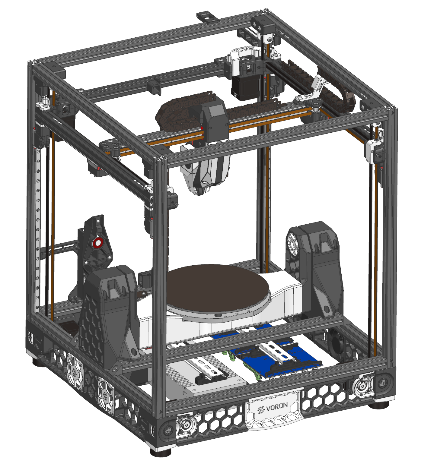
Current status:
Mechanically and electrically, everything works. For the setup process I put it in the standard coreXY mode M669 K1. Homing for all the axis works perfectly (A- and C-axis do also have homing switches). A is constrained +/- 90°, C is free to rotate indefinitely.Problem:
In my research concerning the feasibility of the project I stumble upon all the duet documentation regarding the "robot" stuff: Robot Docs. I found my way to the 5-axis CNC page (5-axis Docs) and discovered a already existing configuration for CoreXYAC. So the command M669 K13 B"robotType=CoreXYAC" should solve all my problems.
Turns out I was a bit too optimistic there. When implementing M669 within the config.g file I get the following message:
Am I correct in the assumption that those types are not implemented in RPF 3.4.5 or are other previous configurations needed before the M669 command?
So even if I must configure the kinematics matrix myself, it's hard for me to find the correct information, as it's obviously quite a niche application and the information is fragmented across different pages. For example: The M669 command is featured much more in depth on the robot config page than on the gcode repository for M669.
If someone already has any help, insight or information regarding this topic, your support would be much appreciated.Thanks in advance
DanPS: I looked a lot at the OpenX5 repository from Freddie Hong but all the kinematics stuff is handled in the grasshopper/ rhino setup and not on the Duet. Due to the fact that we are planning to use commercial 5-axis slicing software this is not really a option. This printer needs to receive XYZAC lines and to move according to the kinematics model.
-
RE: TMC2209 and Nema14 tuning / noisy and vibratingposted in Tuning and tweaking
@noobydp
I got theses ones: aliexpress
They matched the original sigma nema 14 steppers the closest. The manufacturer stepperonline is reputable and also has its own webshop. Depending on where you life and how much time you want to wait on your steppers the webshop ist the better place to order from. -
RE: TMC2209 and Nema14 tuning / noisy and vibratingposted in Tuning and tweaking
@nie-ls
Yes swapping out the motors did actually help. Totally forgot to close this thread...
Now they are whisper quiet in stealthChop mode as they should be. Searching a problem with the most obvious solution is time not well spent. In your case I would suggest swapping out the motors too. I don't know what was wrong with mine, but I could instantly feel the difference between old and new when turning the drive shaft by hand. No resistance or indexation. Due to the fact that even damper mounts can't help in your case, I would clearly point the finger at your NEMA 17s. If you have an other NEMA17 variant to swap out, try that. Otherwise they are not too expensive, as long as you don't use any special variety. -
RE: TMC2209 and Nema14 tuning / noisy and vibratingposted in Tuning and tweaking
@lem
I have tried playing around with the blank time (M569 B) and the off time (M569 F). Between these two and the minimum step puls width (M569 T a:b for TMC2209) I suspect the solution for my problem. However playing around with the T parameter is not easy because it needs to match with the other parameter combination or the control will not accept the change (bad timing error). The only way to analyse all those changes correctly would be to have a readout on a oscilloscope. But I don't have one and wouldn't be able to interpret the results anyway.
I will have at least some clarity on my theory once the new motors arrive and they behave differently or the same. -
RE: TMC2209 and Nema14 tuning / noisy and vibratingposted in Tuning and tweaking
@droftarts
So I did some test prints and there were VFAs but not as bad as I would have excepted, considering the sometimes absolutely frightening resonance while the X or U axis were moving. It was actually hard to take a picture of them because they were barely noticeable. I don't have any input shaping configured yet. And some slicer settings will definitely be addressed.

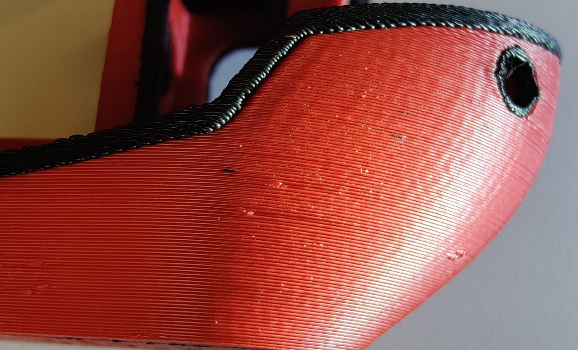
I also played around with the StealthChop settings that were suggested in the TMC2209 paper. However I could't notice any impact .So I blindly tested different values for the hysteresis settings, as well as blank and off times. Good news, the motors are still alive. Bad news, I couldn't make out a difference. I got them back to the settings I started off with.
I ordered some new Nema14s. Will be interesting to see if that makes a difference and if it was a hardware problem all along.
-
RE: TMC2209 and Nema14 tuning / noisy and vibratingposted in Tuning and tweaking
@droftarts Thank you very much. I just finished the XYU offset calibration and will start shortly with some normal test prints. I'll post my results.
-
RE: TMC2209 and Nema14 tuning / noisy and vibratingposted in Tuning and tweaking
@dc42 That's correct I'm using 24V, Fluke says so too. And all the other steppers are whisper quiet.
I don't know if I would just be better off buying new Nema14s but then there's no guarantee that this would solve anything. BCN3D got it working so this has to be one or more of the parameters I was too afraid to change up until now. I just don't really know what the different parameters (except D and V, H is irrelevant for TMC2209 anyway) actually do and what value to set it back to if it gets worse. And I don't want to burn the coils crispy. There is also not a lot of literature and guides for non electrical engineers around which could help me as a novice. -
RE: TMC2209 and Nema14 tuning / noisy and vibratingposted in Tuning and tweaking
@droftarts I consulted that but as you say it's incomplete. If there are no standard values it's hard to start somewhere because if it does not work you don't know what value to set it back to. That's why I was hoping someone already had to do this before.
@o_lampe The wires are correct, otherwise the coordinates would all be messed up and this is not the case.
Here are two videos. One with the U axis motor and one with an external stepper (same model). The speed sweep begins at 100mm/min and goes up to 8000mm/min.
!Audio WARNING!In the last video you can really see (and hear) that the stepper is vibrating like crazy.
-
RE: TMC2209 and Nema14 tuning / noisy and vibratingposted in Tuning and tweaking
@droftarts
I just updated yesterday from 3.3 to 3.4.M115 FIRMWARE_NAME: RepRapFirmware for Duet 3 Mini 5+ FIRMWARE_VERSION: 3.4.2 ELECTRONICS: Duet 3 Mini5plus WiFi FIRMWARE_DATE: 2022-09-13 15:14:33I already tuned for the switchover velocity. It's in the first code window if you scroll down. But I'm wondering if I can change the other parameters of M569 and what effect each of them actually has on the motor performance (T,F,C,B,Y). I hoping someone here already had to do a deep dive once. Because I don't think it's a mechanical problem of the motors or they would not have worked in the original Sigma. I had a look at the BCN3D firmware but I don't know my way around Marlin firmware and where to look for those parameters.
-
RE: TMC2209 and Nema14 tuning / noisy and vibratingposted in Tuning and tweaking
@o_lampe
I have tried as low as 400mA, but then there is absolutely no torque left.
I also did some more tests. The noise is amplified by the mechanical resonance of the XU gantry with the first resonance at about 30mm/s and then obviously the multiples 60, 90 and so on. But a little Nema14 should not be exciting the gantry like that. And I mean I got it better with some tweaking so there must be something that could be done. Mostly because the stepper is vibrating like in fullstep mode. I have the exact motor separately and if I plug it in as the X or U motor and hold it in my hand while conducting a speed sweep from 2 to 100mm/s, there is only some audible noise from the motor but it's shaking my hand like a 2$ electric toothbrush. Maybe there is something to be done with input shaping, but I think that's a band-aid solution and won't work because the resonance is a constant and not only an acceleration problem.PS: just had a look at the old BCN3D marlin versions. They drove them at 750mA.
// Motor Current setting (Only functional when motor driver current ref pins are connected to a digital trimpot on supported boards) #define DIGIPOT_MOTOR_CURRENT {135,135,135,135,135} // Values 0-255 (RAMBO 135 = ~0.75A, 185 = ~1A) -
TMC2209 and Nema14 tuning / noisy and vibratingposted in Tuning and tweaking
Hi guys.
So I'm having a bit of trouble with two Nema14 stepper motors and the TMC2209 drivers. They run loud and vibrate a lot. With the standard settings I was afraid some screws would vibrate loose. The two steppers are for the X and U carriages on my new IDEX build (BCN3D Sigma R16 overhaul). I was able to tune the Z, Y and E steppers without any problems, but those are Nema17. I followed the guide on driver tuning and played around with M569 and M915. But somehow the Nema14s refuse treatment. It's better than the standard settings but still not acceptable. I also looked at the TMC2209 datasheet but 80 pages of not knowing what to look for and not understanding a thing is a difficult combination.
Datasheet Nema 14:

Relevant parts form my config file:; Configuration file for Duet 3 Mini 5+ (firmware version 3.3) ... ; Drives M569 P0.0 S1 ; physical drive 0.0 goes forwards M569 P0.1 S0 ; physical drive 0.1 goes backwards M569 P0.2 S0 ; physical drive 0.2 goes backwards M569 P0.3 S0 ; physical drive 0.3 goes backwards M569 P0.5 S0 ; physical drive 0.5 goes backwards M569 P0.6 S0 ; physical drive 0.6 goes backwards M584 X0.2 Y0.1 Z0.0 U0.3 E0.5:0.6 ; set drive mapping M350 X16 Y16 Z16 U16 E16:16 I1 ; configure microstepping with interpolation M92 X80 Y80 Z1600 U80 E400:400 ; set steps per mm M203 X10000 Y10000 Z1500 U10000 E5000 ; set maximum speeds (mm/min) M566 X750 Y750 Z60 U750 E900 ; set maximum instantaneous speed changes (mm/min) M201 X1000 Y1000 Z200 U1000 E1200 ; set accelerations (mm/s^2) M906 X800 Y1400 Z1100 U800 E650 I30 ; set motor currents (mA) and motor idle factor in per cent M84 S60 ; Set idle timeout ; Motor Tuning ; Z-Stepper M569 P0.0 D3 V2000 ; stealthChop2 on, switch to spreadCycle at 0.2mm/s M915 P0.0 T2000 ; Y-Stepper M569 P0.1 D3 V50 ; stealthChop2 on, switch to spreadCycle at 187.5mm/s M915 P0.1 T50 ; X-Stepper M569 P0.2 D3 V50 ; stealthChop2 on, switch to spreadCycle at 187.5mm/s M915 P0.2 T50 ; U-Stepper M569 P0.3 D3 V50 ; stealthChop2 on, switch to spreadCycle at 187.5mm/s M915 P0.3 T50 ; E1-Stepper M569 P0.5 D3 V100 ; stealthChop2 on, switch to spreadCycle at 18.8mm/s M915 P0.5 T100 ; E2-Stepper M569 P0.6 D3 V100 ; stealthChop2 on, switch to spreadCycle at 18.8mm/s M915 P0.6 T100Console returns for X and U:
M915p0.3
Driver 0.3: stall threshold 1, steps/sec 200, coolstep 32, action on stall: none

M915p0.2
Driver 0.2: stall threshold 1, steps/sec 200, coolstep 32, action on stall: none

M569p0.3
Drive 3 runs in reverse, active low enable, timing fast, mode stealthChop, ccr 0x00053, toff 3, tblank 0, tpwmthrs 50 (187.5 mm/sec), pwmScaleSum 9, pwmScaleAuto 0, pwmOfsAuto 36, pwmGradAuto 14, pos 24

M569p0.2
Drive 2 runs in reverse, active low enable, timing fast, mode stealthChop, ccr 0x00053, toff 3, tblank 0, tpwmthrs 50 (187.5 mm/sec), pwmScaleSum 9, pwmScaleAuto 0, pwmOfsAuto 36, pwmGradAuto 14, pos 8
Thanks in advance if anyone knows this stuff and is able to help me.
-
RE: Duet 2 Wifi on a Wanhao Duplicator 6?posted in Duet Hardware and wiring
@jith No I did not. But mounting the mosquito to the D6 involved milling off part of the original printhead and drilling some accurate holes. So you would need access to a machine shop or milling machine of sorts. And you will cross a point of no return because there are not a lot of spare D6 printheads flying around (tapping M2.5 threads gets really interesting)
 . If you are interested I can send you all the CAD files so you can have a look.
 -
RE: IDEX wrong extruder motor turningposted in Using Duet Controllers
Thanks a lot. @deckingman @engikeneer
So it's a little embarrassing but I actually tried that before but it didn't work. Because for me T1 H1 and D1 belong together as do T2 H2 D2... see where I'm going with this. If you aren't accustomed to start index counting from 0 things like this happen
 ...
...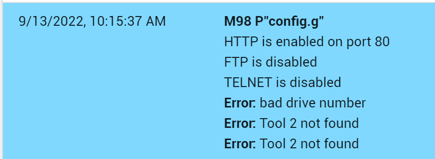
But yes with T1 D0 and T2 D1 everything works just fine.
-
IDEX wrong extruder motor turningposted in Using Duet Controllers
Hi guys.
So I rebuilt a BCN3D Sigma R16 from scratch. I got it for free because it was stripped for replacement parts. Basically just the linear rails and the Z-axis assembly were left.
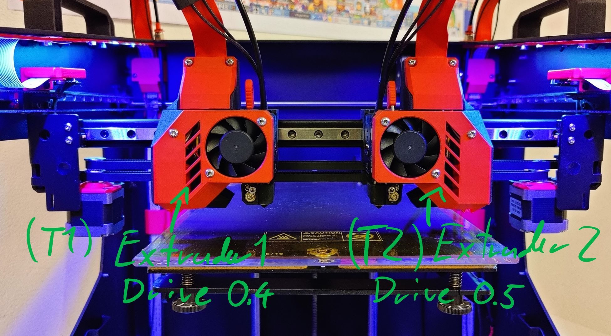
I mostly got it working with the U-axis and all, however there is one problem I can't understand yet.
If I switch to T1 (left extruder) everything works fine if i give an extrude command (G1 E10 F300). However if I switch to T2 (right extruder) and give the same command, the left extruder motor from T1 turns and not the right one from T2.
T1 is mapped to drive 4 and T2 to 5.
Its not that the drive is faulty.
If i plug and map the X-axis on drive5, I can move it without problems.
It's not an extruder motor problem because it works fine if I plug it in drive 4.
Next I tried the mixing stuff aka M567 with E0:1. Doesn't work.
Also just (G1 E0:10 F300) gives the array too long error.
So I don't know if I messed up in the config or misunderstood the IDEX guide .
If someone has an idea on how to get extruder 2 turning please let me know
Thanks in advance.Here are the relevant parts of the config file. Heater, Fans and tempsensors on T2 work just fine.
; Configuration file for Duet 3 MB 6HC (firmware version 3.3) ; executed by the firmware on start-up ; ... ; Drives M569 P0.0 S1 ; physical drive 0.1 goes forwards M569 P0.1 S0 ; physical drive 0.2 goes backwards M569 P0.2 S0 ; physical drive 0.3 goes backwards M569 P0.3 S0 ; physical drive 0.4 goes backwards M569 P0.4 S0 ; physical drive 0.5 goes backwards M569 P0.5 S0 ; physical drive 0.6 goes backwards M584 X0.2 Y0.1 Z0.0 U0.3 E0.4:0.5 ; set drive mapping M350 X16 Y16 Z16 U16 E16:16 I1 ; configure microstepping with interpolation M92 X80 Y80 Z1600 U80 E400:400 ; set steps per mm M203 X10000 Y10000 Z1000 U10000 E5000:5000 ; set maximum speeds (mm/min) M566 X750 Y750 Z60 U750 E900:900 ; set maximum instantaneous speed changes (mm/min) M201 X1000 Y1000 Z200 U500 E1200:1200 ; set accelerations (mm/s^2) M906 X750 Y1400 Z1100 U750 E650:650 I30 ; set motor currents (mA) and motor idle factor in per cent M84 S60 ; Set idle timeout ; Axis Limits M208 X-20 Y0 Z0 U0 S1 ; set axis minima M208 X205 Y295 Z200 U225 S0 ; set axis maxima ... ; Heaters M308 S0 P"temp0" Y"thermistor" T100000 B4138 ; configure sensor 0 as thermistor on pin temp0 M950 H0 C"out0" T0 ; create bed heater output on out0 and map it to sensor 0 M307 H0 B0 R0.364 C334.5 D2.24 S1.00 ; disable bang-bang mode for the bed heater and set PWM limit M140 H0 ; map heated bed to heater 0 M143 H0 S120 ; set temperature limit for heater 0 to 120C M308 S1 P"temp1" Y"pt1000" ; configure sensor 1 as PT1000 on pin temp1 M950 H1 C"out1" T1 ; create nozzle heater output on out1 and map it to sensor 1 M307 H1 B0 R2.683 C270.1 D6.12 S1.00 ; disable bang-bang mode for heater and set PWM limit M143 H1 S450 ; set temperature limit for heater 1 to 450C M308 S2 P"temp2" Y"pt1000" ; configure sensor 2 as PT1000 on pin temp2 M950 H2 C"out2" T2 ; create nozzle heater output on out2 and map it to sensor 2 M307 H2 B0 R2.799 C266.8 D5.32 S1.00 ; disable bang-bang mode for heater and set PWM limit M143 H2 S450 ; set temperature limit for heater 2 to 450C ; Fans M950 F0 C"out3" Q65535 ; create fan 0 on pin out3 and set its frequency M106 P0 C"Extruder Fan 1" S0 H1 T50 ; set fan 0 name and value. Thermostatic control is turned on M950 F1 C"out5" Q65535 ; create fan 1 on pin out5 and set its frequency M106 P1 C"Part Fan 1" S0 H-1 ; set fan 1 name and value. Thermostatic control is turned off M950 F2 C"out4" Q65535 ; create fan 2 on pin out4 and set its frequency M106 P2 C"Extruder Fan 2" S0 H2 T50 ; set fan 2 name and value. Thermostatic control is turned on M950 F3 C"out6" Q65535 ; create fan 3 on pin out6 and set its frequency M106 P3 C"Part Fan 2" S0 H-1 ; set fan 3 name and value. Thermostatic control is turned off ; Tool 1 M563 P1 S"Exruder 1" D0.4 H1 F0:1 ; define tool 1 G10 P1 X0 Y0 Z0 ; set tool 1 axis offsets G10 P1 R0 S0 ; set initial tool 1 active and standby temperatures to 0C ; Tool 2 M563 P2 S"Extruder 2" D0.5 X3 H2 F0:3 ; define tool 2 on U-axis G10 P2 U0 Y0 Z0 ; set tool 2 axis offsets G10 P2 R0 S0 ; set initial tool 2 active and standby temperatures to 0C ; Custom settings are not defined -
RE: Dual hotend, one motor possible?posted in Duet Hardware and wiring
Perfect... I'll get going then
