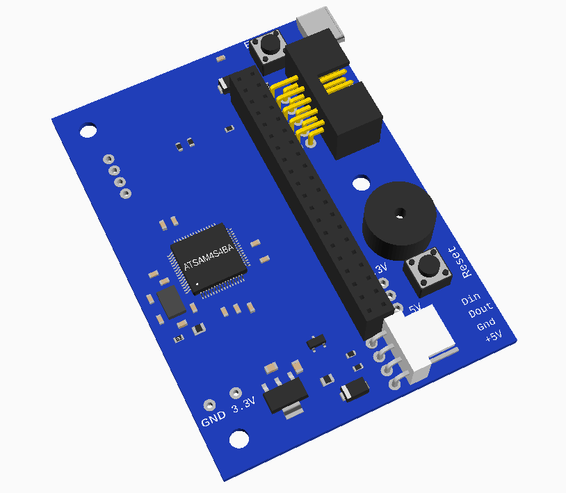
I have added the Model to NopSCADlib if anybody needs an OpenSCAD model.

I have added the Model to NopSCADlib if anybody needs an OpenSCAD model.

@deckingman said in Continuous vertical lines on shell:
coupled with the lower torque available for partial full steps (due to micro-stepping) might mean that the motor will have a tendency to jump to the nearest full step. i.e. small (say single digit) micro steps might not necessary translate into any physical movement of the motor.
This is a common fallacy / misconception that is all over the web. The torque available when microstepping is the same as full steps because the vector sum of the two coil currents is always the same. I.e. the peak current when only one coil is on is sqrt(2) times the current when both coils are on. So at any stop position the holding torque is the same. It isn't less at intermediate microstep positions.
It is true that the torque is always proportional to displacement from the rest position, so if you only move a very small step the torque applied is very low and may not overcome stiction. However that is only relevant at the start. If the the load does not move the displacement quickly increases and so does torque until it does move.
Once moving at constant speed the rotor lags the rest position by an amount that generates enough torque to overcome the dynamic friction. If that lag exceeds two full steps the motors stalls because the torque is sinusoidal so reaches a maximum. During acceleration it lags more and during deceleration it leads.
I use single outlines and make all my holes polyholes, see http://hydraraptor.blogspot.com/2011/02/polyholes.html. Then they always come out the exact size I want.
Yes but you also need to limit the number of sides to about twice the hole diameter in mm.
When the nozzle turns a corner the filament likes to take a shortcut and cut the corner, making it rounded. When you have a less corners they are further from the desired circle, so when they get rounded they are still outside it. I found empirically that when the number of sides is twice the diameter the rounded corners just about lie on the circle, so you get the roundest hole that is still the right size.
Since I design exclusively on OpenSCAD it is not problem for me to make all holes with poly_cylinders instead of cylinders. My STL files then print correctly with any slicer and toolchain.
When printing other peoples designs, my old machines that run from my own host and firmware have the ability to detect circles in the g-code and convert them. That enabled me to print thousands of Mendel parts without having to ream all the holes.
@asdasd1234 Do you have control over the number of line segments in the STL file? I have noticed with Cura it will generate ridiculously short segments if the model has them. As I model in OpenSCAD I can simply set $fs to half my extrusion width and then I don't get any segments shorter than 0.25mm. There really isn't any point in printing shorter segments. Skeinforge combines segments that are too small, not sure about other slicers.
@dc42 said in Laser filament monitor:
We might be willing to supply one of our prototypes to a user who meets the following conditions, to try to speed up finishing it:
I think I meet those requirements and would like to test one of these.
What is the timescale for production Duet 3's? I am designing a machine that has some CAN peripherals but I won't finish it anytime soon.
I like the idea of a small firmware that just does the realtime stuff and the rest on an SBC in Python. That is how my early machines work, including HydraRaptor and the very first Mendel90.
It is actually behaving like one of the sockets is shorted. The motor plugged into that one would not spin but the other would.
@thugmek The simplest solution is print ABS brackets. I run my motors so they have a 20C rise but they are in a 45C chamber, so they get to 65C. ABS is fine with that.
@dc42 The motion planning does not need to be realtime, only the actually stepping of the motors. As long as the data is produced fast enough to keep a buffer full it works. I sent trapezoids to my real time code encoded as a list of step durations during the ramps, the constant speed step duration and the total number of steps. My reatime code just did the Bresenham loop. Never had to change in more than 10 years and only needs a tiny 16 bit micro.
I have added the Model to NopSCADlib if anybody needs an OpenSCAD model.

I can't find the design files for the Panel Due v3.0a PCB that I have. I would like to model the board in OpenSCAD and having the Gerber files saves a lot of time.
Are the available on github?
R in the equation is the resistance of the thermistor at temperature T, they are the variables. A, B, C are constants for a given thermistor.
When T is 25C then R will be the thermistor's nominal resistance, e.g. 100K.
@Nuramori Ha, Skeinforge has had that option for about 10 years I think.
@zapta said in Duet 3 first-generation prototype giveaway:
@nophead said in Duet 3 first-generation prototype giveaway:
No it doesn't because motion planning does not depend on real time input,
How do you handle motion related configurations that are done at the printer's level? E.g. from config.gcode? Do you feed them to the off line planner?
Sorry I missed this question a month ago.
My machine specific configuration is simply expressed in Python files, rather than encoded into dozens of cryptic gcodes. When I process the machine agnostic g-code tool path from the slicer I apply the machine and filament specific speeds, accelerations and temperatures, etc, before sending binary packets to the actual machine.
I never modify anything on the fly though. I have never felt the need. When I start a print job it is usually from another room. I tend to look via camera to see if the first layer looks sane and then I wait for it to finish. I don't interact with my machines other than to clear the bed ready for the next job, or change the filament. I run a separate python script to do the latter.
As well as the spring effect of filament and motor there is also backlash if using gearing or a Bowden tube that has to be slightly bigger diameter than the filament. @dc42 does the pressure advance separate these two effects and compensate for them independently? I.e. to get over backlash you would want a very fast movement and then a slower accelerating speed once the filament is engaged.
@robm If the lines are aligned vertically they are related to stepper position. I don't see how varying speed or acceleration would change the position of the lines, just perhaps their severity if they are due to resonance.
On a delta the motor positions don't map linearly to object position, breaking alignment, but on a Cartesian machine there is no way to break the alignment.
@jens55 said in Can 'pressure advance' cause negative filament feed ?:
negative feed doesn't make sense
It does if the line segment is a very short part of a decelerating sequence as dc42 explained. During deceleration the pressure has to be reduced and that means feeding less filament in than is coming out. The amount extruded during the line should always be positive and proportional to its length but that isn't the same as what is feed into the extruder while accelerating and decelerating with pressure advance.
However, in any sequence of segments from a start to a stop the total fed in should equal the total out, so that should always be positive and match the sum of the E values in the G-code.
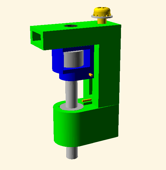
This is what I use on one of my machines.

It is a 4mm rod that runs in an LM4UU bearing and is held above the nozzle by a magnet. When I remove a print I manually deploy it by pulling it down away from the magnet. It then closes two gold contacts together and hangs below the nozzle.
When I start the next build my host software checks the contacts are closed and prompts me if I have forgotten to deploy it. It then probes the bed using successive approximation to find the z microstep where the contacts just open.
When it has finished probing it lowers Z axis until the probe is attracted to the magnet, which lifts it clear of the nozzle.
Is it too simple?