So sorry to hear it. Rest in Peace.
Posts made by mrehorstdmd
-
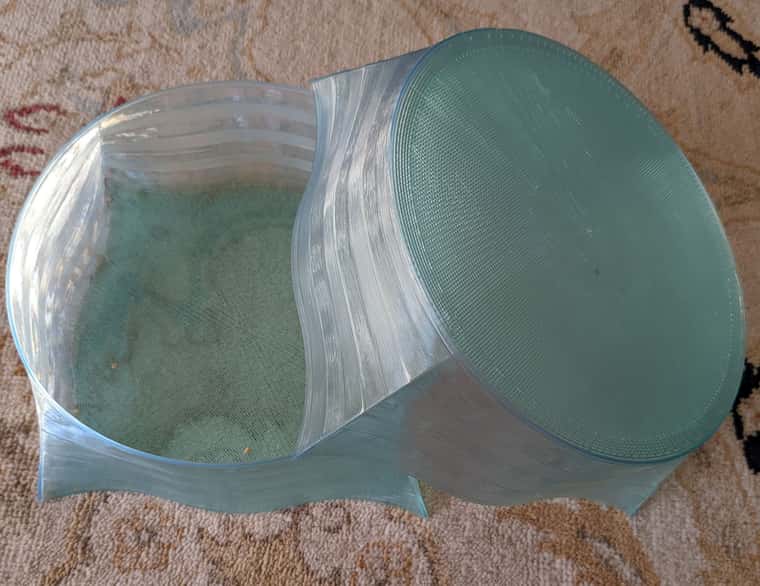
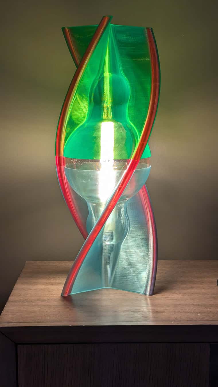
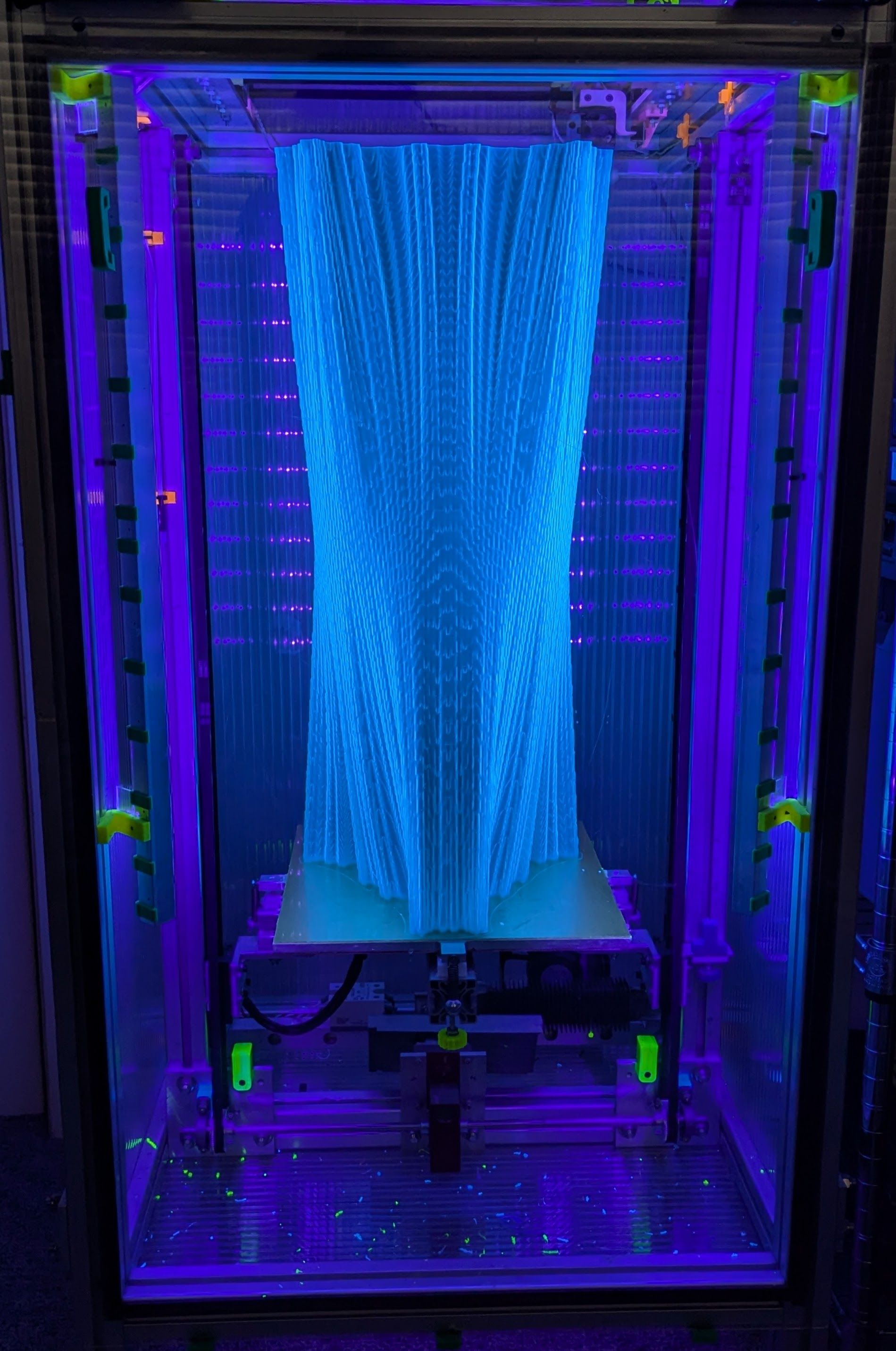
My biggest print yet on UMMD
15 hours at 40 mm/sec, 1mm nozzle, 1.2 mm line width, 0.3 mm layers, vase mode in Cura, 923g of PETG filament, 638 mm tall:
It's going to become a lamp.
-
RE: My Second build (in progress)
@Dad003 I thought you were trying to simplify the design. Never mind.
-
RE: My Second build (in progress)
@Dad003 click on "one of these" in the post above. That guy has been selling the things via ebay for many years.
Your design may work, but look at all the parts and space required. The worm gear box with attached motor is as simple as it gets. -
RE: My Second build (in progress)
@Dad003 One of these will make your life much easier. The 30:1 reduction enables it to lift very heavy beds, and it doesn't move when the motor is disabled, allowing restart of prints in the event of a power failure. It doesn't require brakes, additional wiring, or additional configuration. Just treat the motor like a normal stepper. I used 60 tooth pulleys on the shaft to get 20 um per full step from the motor. I've been using it for my 695 mm Z-axis about 7 years without any problems. The gear quality is very high, so there are no gear induced artifacts in the z-axis of prints.
-
RE: My Second build (in progress)
@Dad003 You can simplify construction and probably reduce mass by using rectangular aluminum tubing to make the two pulley blocks at the ends of the axis. You can use it for motor mounts, too.
If you bolt the t-slot pieces directly to each other you won't need all those corner braces. Tap the ends of the inside t-slot pieces, and drill tool-access holes at appropriate locations in the outside t-slot pieces. You can use button head cap screws with washers in the slots to connect two pieces together. This assumes that the ends of the pieces are cut/milled square. See: https://www.youtube.com/watch?v=HfcXjYWw5UQ
-
RE: DWC no longer connects to my laptop
I have found that it's very hard to maintain connection to the Duet board via wifi network if the computer I am using has VPN switched on.
-
RE: Ihsv42
@4eIIIuP Here are some of my test prints. I don't recall all the settings used, but my blind tuning of the motors didn't improve anything. You probably know more about tuning servos than I do...
Test print made with 400 step/rev steppers at 160 steps/mm:
Test print made with IHSV-42 servomotors at 500 steps/mm:
Test print made with IHSV servomotors and 3:1 reduction. This print was made at 4000 steps/rev, 3:1 drive reduction, 300 steps/mm, 50 mm/sec, with accel 5000 mm/sec^2, 0.2 mm layers, 1mm line widths:
Motor mount with 3:1 belt reduction:
I believe I've seen other photos of prints made using these motors in this forum and they looked great, but I've never seen the details of the mechanical setups or the motor parameter settings, either dip switches or firmware.
In the flat areas of the prints I didn't see the same artifacts you're getting- those might be caused by a dual drive extruder or by using too small pulleys in the XY mechanism. I use F608 skate bearings for pulleys and don't have that problem, but the dual drive extruder causes a wood-grain appearance in prints:
-
RE: Ihsv42
@4eIIIuP In my tests I didn't see problems with straight sides, but did see a lot of "salmon skin" in curved surfaces which I ultimately attributed to poor resolution of the servo motors. I was not able to find much useful info on tuning the motors. I made one more test in which I used a 3:1 belt drive reducer to improve the resolution, but still could not get it to deliver the same print quality as my 400 step/rev steppers, and ultimately gave up on the servos.
One nice thing about the servo motors- they were super quiet. The only sound from the printer was the sliding of the corexy mechanism and the hot-end fan.
The IHSV servos work great in my sand table where the resolution isn't really important, but speed and noise are.
-
RE: To build another printer or not !
@Dad003 6 steppers? If you want high speed and quiet operation, use just two servomotors instead of 6 steppers. Electronics will be simpler and probably cheaper, and it will work better.
I use some cheap 24V, 78W, Chinese servos in my corexy sand table and it can run at 1500 mm/sec. If I installed larger drive pulleys, it could go much faster. Those servos aren't very good for 3D printing (I've tried) , but there are better ones that are. Look at Clearpath. Servomotors can give more than adequate torque to move a 3D printer mechanism at 3000 rpm.
At high speeds (anything over about 200 mm/sec) the belts hitting the pulley teeth are going to make zipping noise no matter what you do. For minimum noise, make the drive pulleys the only ones that the belt's teeth engage. Put twists in the belts so that smooth back of belt runs on smooth pulleys made from stacked ball bearings. Jerk and acceleration are also going to contribute to noise, especially if you want to print at very high speed. Every time a motor reverses direction it's going to go "bang".
I wouldn't use 24V for a bed heater. Why go to the expense of using a regulated power supply to power a resistor? Use line power with an SSR. The same goes for a chamber heater, especially if you want to print ABS.
For the belt lifted Z axis, I get great results from a 30:1 worm gear drive. It is as simple as you can get- the worm gear can't be back driven by the weight of the bed, so when power is cut the bed just sits there. It doesn't drop or move. No brakes, no messing around. Set the steps per mm and it just works. The Duet boards can drive the 24V NEMA-23 motor directly, so no additional motor drivers, wiring, and power supplies are needed. The gears in the drive are very high quality and don't produce any Z artifacts in the prints.
Will that footprint let the machine fit through doors?
-
RE: automatic 3 axis bed levelling: kinematic versus maxwell mount
@stellator Your first illustration is a Kelvin type kinematic mount. Both Kelvin and Maxwell mounts accomplish the task of allowing the bed plate to expand laterally without bending any mounting screws or causing the plate to flex or lift. The main differences between them are that the Maxwell mount reference point is at the intersection of the three grooves while the Kelvin mount reference point is at the hole or cone in which a ball sits. The other difference is that the Kelvin mount axes can be aligned with the X and Y axes in a machine making it especially easy to tram the bed because adjustment to the roll doesn't affect the pitch of the plate. With a Maxwell mount the axes are usually aligned 120 degrees apart so adjustments at any one point affect both the pitch and roll of the bed, making tramming a little trickier.
This is the bed support in my printer, designed as a Kelvin kinematic mount. The axis with the two spherical screws is aligned parallel to the printer's X axis. One of those balls (the reference) sits in a hole in the bed plate, the other (the pitch adjuster) in a groove that runs parallel to the X axis. The third point (roll adjust) is just a screw that touches the smooth bottom surface of the bed plate. The bed plate has ears for the three adjusters/support screws and is held down on the screws by springs. The reference screw doesn't normally get adjusted when tramming the plate. Tramming is done with a piece of paper between the bed plate and extruder nozzle. Simply adjust the Z position of the nozzle near the reference screw until it just catches the paper, then move the nozzle along the X axis until it is near the pitch adjuster and adjust until it just grabs the paper. Finally, move the nozzle near the roll adjuster and adjust until the nozzle just catches the paper and it's done. The last time I trammed my printer was almost 2 years ago.
The reference screw sitting in its hole in the bed plate:
Here's the whole thing:
All three adjusters are mounted in PTFE blocks that grip the screws firmly but still allow them to be turned for tramming. They also don't mind the heat from the bed plate. If you make anything like this, don't use nylon instead of PTFE. you won't be able to turn the screws (I know, I tried). There's a reason they use nylon in nylock nuts! You don't need to tap the PTFE blocks. Just make slightly undersized pilot holes and thread in the screws. They will roll their own threads into the PTFE.
-
RE: A breakthrough in bed levelling design !
@Richard-F That's so one-dimensional, and what? No batteries?!! ! You need one of these:
https://www.amazon.com/Digital-Protractor-DXL360S-Inclinometer-0-01°resolution/dp/B077T7XW7X
-
RE: Note on updating firmware in older boards- check ajax retries!
@chrishamm Thanks! Updated. I'll let it run for a while and see how it goes. I do run a VPN on the computer that is accessing the Duet board. I'll try switching that off and see if it behaves differently.
-
RE: Where to source reliable GT2 30T 10mm belt width pulleys?
My experience with cheap pulleys sourced from China is that the holes are either too large or off center resulting in unwanted motion of the printer mechanism. Idlers that have built-in bearings typically have very small, low quality bearings that won't last, and are likely to have the same off-center hole to mount the bearings. Filastruder sells Gates pulleys that are properly drilled for about $5 each.
If I wanted a toothed idler I would probably buy a Gates pulley, insert a shaft, and mount it in an assembly that uses larger ball bearings. Otherwise, if you don't need toothed idlers, stacked F608 bearings make great pulleys for 10mm belt. They are cheap and will probably last forever in a 3D printer. I've been using them in my printer for 6 or 7 years and they show no signs of problems.
-
Note on updating firmware in older boards- check ajax retries!
My sand table uses a Duet2 wifi board. For a long time it had problems maintaining the wifi connection on multiple wifi systems using different routers. It couldn't stay connected for more than about 1 minute and 7 or 8 seconds. I decided to dig into it again and found mention of the ajax retries in the wifi troubleshooting wiki. I found that setting ajax retries from default 2 to 5 fixed the dropped wifi connection problem.
Yesterday I was commissioning a "new" (version 1.02 hardware) board for a new project and wanted to update the firmware from 2.05.1 to more recent stuff. I got it working on my network, and like the sand table, had to set ajax retries to 5 to get it to stay connected. I went through the recommended sequence on updating to 3.0, then 3.3, and finally 3.4.6 and found that when I updated to firmware 3.3 the ajax retries got reset back to 2 which caused the connection to drop every 1 minute and 7 or 8 seconds until I set it to 5 again.
My current network uses a mesh router that includes sandboxed 2.4 GHz IOT network that I was connecting the duet2 board to, so the router shouldn't be trying to tell the board to reconnect on a 5GHz network.
Is there some reason the default ajax retries is 2 and not some higher number, or is my situation somehow very different from typical?
-
RE: how to join wires together?
@achrn get something like this to hold the wires as you hold the soldering iron with one hand and the solder with the other.
I typically put a single bend in each wire and hook them together, squeezing the bends tight, then solder, then shrink the tubing over them. Never fails.
Wagos are great, but they're big- not the sort of thing you want dangling from your extruder carriage. They are great for wiring the rest of the printer...
-
Arrakis 2.0 Sand Table programmed for cat entertainment
My coffee table, aka Arrakis 2.0, is a servomotor powered coreXY mechanism that is normally used to magnetically drag a steel ball to create pretty patterns in sand. My cat enjoys chasing the ball, especially when the table is running a spiral erase pattern at 1000 mm/sec.
I decided to try to create patterns that she might like, so I wrote a spreadsheet that generates random motion of the type that attracts her attention. I enter the table dimensions, the desired speed range, and desired dwell time range and the spreadsheet creates gcode that causes the ball to move in random directions at random speeds and then stops for a random amount of time, before darting away, sort of like a small animal might behave. Ms. Kitty loves it!
The spreadsheet generates 500 lines of gcode that typically take about 16 minutes to run on the table, about 3x longer than Ms. Kitty's attention span.
More: blog post
-
RE: Weird extrusion issue
@LeonMF It looks like both the extruders you mentioned are dual drive type.
Have you seen this: https://youtu.be/32dTLRNIYmw?si=d5yZB3FCSG-k59EY ? -
RE: Chamber circulation fan control
@travasky said in Chamber circulation fan control:
@mrehorstdmd how are you getting around the fans turning off / pulsing when the chamber hits the target temp? In the original machine fans were on 100% of the time the machine was on. In my case I'd like the ability to control them if I decide to print a material other than ABS for example. I added a heated bed to give me flexibility on materials instead of the plastic build plate that was passively heated on the original. Seems like a shame to not be able to use or not use the fans at will.
I don't. The fan turns on and off with the heater. The printer is tall and the heater/fan located at the bottom of the machine. I only heat to 50C when printing ABS and don't want a lot of air movement at the print, so for my printer, it's fine that the fan is low powered and doesn't spin continuously.