@jay_s_uk This thread is the first one we find on Google when doing a search for this issue, it's better for everyone if the information stays in one place no matter when it came from.
I'd really like an answer to this problem if you don't mind 
Posts made by MrDui
-
RE: Warning: motor phase B may be disconnectedposted in Duet Hardware and wiring
-
RE: Warning: motor phase B may be disconnectedposted in Duet Hardware and wiring
@dc42 said in Warning: motor phase B may be disconnected:
if you get warnings for both phase A and phase B then they may be false positives,
I think I am exactly in this case right now: the printer works fine, but it reports error on the Z axis for all three motors :
Warning: motor phase A may be disconnected reported by driver(s) 5 6 7
Warning: motor phase B may be disconnected reported by driver(s) 5 6 7Is there a way to fix it that you would be aware of?
Thanks !
-
RE: Advanced nozzle designposted in 3D Printing General Chat
Very interesting and pretty cool tools you got there!
What about maximum flow comparison between both nozzles? -
RE: Input Shaping makes no difference whatsoeverposted in Tuning and tweaking
@deckingman said in Input Shaping makes no difference whatsoever:
@mrdui I have a theory which is purely conjecture, and based on two things that you have mentioned. Firstly that your print head has a mass of 8Kgs and secondly that you only see the artefacts when printing detailed parts. So it could be that small, probably segmented moves, start and end at some micro-stepping value in between full steps.
Sorry I should have been clearer: ringing only bothers me when I do details parts because the goal of detailed parts is usually to get a good aesthetics result.
But most of the time I print functional parts so I just don't care about the appearance, My only concerns is for the parts to be mechanically sound and to print as fast as possible. But the ringing is the same no matter what parts I'm doing, even when the parts are gigantic.Out of curiousity, what is this print head that has a mass of 8Kgs? I have a 6 input, liquid cooled hot end with parts made from stainless steel and brass as well as aluminium, mounted on a metal gantry between two parallel rails but that only has a moving mass of around 2Kgs. Above that, I have 6 extruders mounted on a separate gantry (the UV axes) which weighs in around 3Kgs. The combined mass of both gantries is around 5Kgs so I'm curious to know what your configuration is that has a mass is 8Kgs.
Actually 8 kilos is the mass of the whole gantry system, so thats the carriage itself, the tubes, the linear bearings, the rollers and the motors. Basically everything that moves, besides the bed. The carriage just by itself is more around 2kilos.
Here is a link to my build thread, in case you're interested to see: https://forum.v1engineering.com/t/mpcnc-made-in-china-new-build/19393/508Most of the weight actually comes from the metal tubes which are very heavy duty industrial smooth rods. Reason being that I was using the previous version of this machine as a CNC router too.
-
RE: Input Shaping makes no difference whatsoeverposted in Tuning and tweaking
@deckingman said in Input Shaping makes no difference whatsoever:
@mrdui Maybe what you are seeing isn't ringing at all. In fact, with an 8Kg print head I'd be very surprised if it is. Have you tried printing at different speeds to see if the pattern changes?
Yes, as suggested earlier by @oliof .
-
RE: Printer actions after filament run outposted in Tuning and tweaking
@tratoon said in Printer actions after filament run out:
Hello. I need some help creating a filament-runout.g. When the printer runs out of filament, I would like it to move the bed down my 10mm, then move to X0 Y0 and pause, then wait for filament to be loaded, then home X and Y ONLY, and then when I press the resume print button, it should resume.
I wouldn't home X and Y because it would be likely to introduce some inaccuracies (limit switches positions aren't totally repeatable).
Is there a specific reason why you'd want to do that?On my printer I just resume the print from wherever the print head was parked during the filament change procedure. Just mke sure the steppers stay energized long enough and at sufficient power so they hold their position and everything should be fine.
-
RE: Input Shaping makes no difference whatsoeverposted in Tuning and tweaking
@gloomyandy said in Input Shaping makes no difference whatsoever:
@mrdui Unfortunately whatever is happening on your setup is not a simple problem, input shaping certainly works on my own setup (which includes a height map, so I don't think that is the problem). The only difference I can see is that I either set the input shaper values directly in my config.g file (once I have tuned them), or set them manually via the console during tuning. I would suggest that you try that (simply enter the M593 command plus the required parameters in the console during the test print), to see if that works for you. Perhaps as suggested above the mass of your print head means that input shaping simply does not work?
I've already tried that, unfortunately it didn't work.

It would be a bummer if it couldn't work on high mass setups, those are arguably the ones that need input shaping/inertia correction the most (at least I think so).
But I do understand that this is the very beginning of the implementation of this feature, so I'm not complaining or anything, I've been printing hundreds of kilos of plastic with this machine without input shaping over the past few years and I'm very happy with it! The ringing doesnt' bother me 99% of the time, it's only annoying when I try to print some very detailed parts, which rarely happens since most of the stuff I print is functional, not aesthetic.Just reporting some strange behavior in case it helps improving the firmware is all. It could also come from my machine itself, but I assume if it were to be the case I would at least see some difference in the ringing patterns when trying different shapers, the same way I see different patterns after increasing the speed. It's a bit weird
-
RE: Input Shaping makes no difference whatsoeverposted in Tuning and tweaking
@gloomyandy said in Input Shaping makes no difference whatsoever:
@mrdui 20Hz is a pretty low frequency for the input shaper. You might want to try something higher like 40Hz, just to see if that makes any difference. Some of the shapers cover a fairly wide frequency range so even if not on the primary frequency they may still help with the ringing.
I've got the same result with 40Hz, and tried many other frequencies, both lower or higher.

I don't think its a problem of settings anymore, there would be at least some pattern change, it looks like it is just off. -
RE: Input Shaping makes no difference whatsoeverposted in Tuning and tweaking
@oliof said in Input Shaping makes no difference whatsoever:
@mrdui pretty close by, true. I would try with 20Hz mzv and a damping factor 0f 0.1 just to be safe.
Doesn't make any difference at all.
-
RE: Input Shaping makes no difference whatsoeverposted in Tuning and tweaking
@oliof said in Input Shaping makes no difference whatsoever:
@mrdui OK. You can measure the distance between repeats of the ringing (peak-to-peak) and divide your speed by that distance to get the ringing frequency. Compare that to your accelerometer values and let us know what the results are.
The measures indicate about 20 Hz. The accelerometer said 16Hz so I guess it's close enough.
-
RE: Input Shaping makes no difference whatsoeverposted in Tuning and tweaking
@gloomyandy I tried another print to check if the input shapers were active during the print after I click on apply, and it seems like the shaper is active indeed after applying it when I ask using M593. So everything seems to work perfectly normally, aside from the fact I get no actual difference on the print quality of course.
I think the issue might be in the input shaper code somewhere, as suggested by @dc42
So I guess I will have to wait for a fix someday, hopefully.
Let me know if I can be of any help for testing when/if this gets fixed!
Ah also I tried the bed compensation taper (M376) and it worked great, thank you very much @infiniteloop !!
(did no difference on the input shaper after the printer finished tapering though, same results during bed compensation and after tapering was done) -
RE: Input Shaping makes no difference whatsoeverposted in Tuning and tweaking
@oliof said in Input Shaping makes no difference whatsoever:
@mrdui if you modify the speed of the printhead while printing, does the distance of the ringing artifacts change (should be wider when faster)? If not, the artifacts is likely not from printheads vibration but another cause like belt cogging or related phenomenons.
Ok so I did the test and it seems like the artifacts vary depending on the speed, as expected.
-
RE: Input Shaping makes no difference whatsoeverposted in Tuning and tweaking
@infiniteloop said in Input Shaping makes no difference whatsoever:
I think you are looking for M376.
Oh, that's great, exactly the feature I was dreaming of! Thanks a lot for sharing it!
Noob question: should I put this gcode in the config.g or in the bed.g file?
I suppose probably in the bed.g file right after the G29 command ?There's so many features in those firmwares it's hard to keep track sometimes.
Anyway, thanks, that will definitely help, I'll try it right away! -
RE: Input Shaping makes no difference whatsoeverposted in Tuning and tweaking
@oliof said in Input Shaping makes no difference whatsoever:
@mrdui if you modify the speed of the printhead while printing, does the distance of the ringing artifacts change (should be wider when faster)? If not, the artifacts is likely not from printheads vibration but another cause like belt cogging or related phenomenons.
Yeah that's a good question, I wanted to try that but I couldn't remember the command to change the acceleration while the printer is running. Didn't want to edit config.g mid print since I was afraid it might cause some trouble.
I'll try that too and report back -
RE: Input Shaping makes no difference whatsoeverposted in Tuning and tweaking
@dc42 said :
Do you use Z hop? I am looking at change the code so that if a travel move is executed when Z hop has been used before that move, segmentation won't be used on that travel move. So the height at the end of the move will still have mesh compensation applied, but the intermediate points won't. This should be OK provided that the amount of Z hop is greater than the maximum compensation amount in the height map.
I have z hop enabled for every travel <5mm, optional for any travel >3mm. z hop height is currently set up at 0.5mm
Earlier you were mentioning bed compensation, and I have a question regarding how bed compensation works, if you don't mind:
Does it compensate for the bed planeity during the whole print or only for the first few layers?It seems to me, according to the noise my Z axis makes during the print, that it compensates during the whole print, which, in my mind doesn't really makes sense because it would report the bed planeity errors over the whole print, so every face of it is being very slightly deformed.
Wouldn't it be better to compensate the bed deformations for just a few layers that we could define ourselves, the printer gradually correcting by averaging differences layer after layer so it eventually comes down to no correction after a while?
In my opinion that would marginally correct some tiny inacuracies, but more importantly on my machine at least, this would make the Z axis a lot quieter. -
RE: Input Shaping makes no difference whatsoeverposted in Tuning and tweaking
@gloomyandy said in Input Shaping makes no difference whatsoever:
@mrdui Just to be clear did you check the Apply/M593 during a print (as it may do things differently if a print is not active)?
No I did it at idle, I will try during a print tomorrow just to be sure, but I'm pretty confident it will be the same (still gonna try it for good measure)
One thing I noticed is that you have a relatively low acceleration limit set on X and Y. I wonder if that might be preventing input shaping from operating correctly? It might be worth temporarily increasing that limit to see if it changes anything.
Yeah I wondered about that too, I can go higher on accelerations just to try it.
-
RE: Input Shaping makes no difference whatsoeverposted in Tuning and tweaking
@gloomyandy I just did as per your recommendation and it seems like it does apply the input shaper when i press on "apply" then check with M593. But there is still no difference on the print result.
Very weird. -
RE: Input Shaping makes no difference whatsoeverposted in Tuning and tweaking
@dc42 first, let me thank you for everything you're doing, I'm a huge fan of your work and very admirative of the incredible knowledge at both hardware and software you have. Bravo.
I indeed use mesh bed compensation, so there might be something there. Is there any workaround? I really need the bed compensation on this machine because its size makes it difficult to find a mirror flat enough to get consistent good first layers on the whole surface.
Ah also here is my config.g file for you @droftarts :
; Prusa i3 config file for dc42 Duet firmware

; Prologue and  comms section
M111 S0                             ; Debug off
M552 S1;
M550 P"BOx Giant Printer"				        ; Machine name (can be anything you like)
M551 *****                        ; Machine password
;*** If you have more than one Duet on your network, they must all have different MAC addresses, so change the last digits
M540 P0xBE:0xEF:0xDE:0xAD:0xFE:0xAE ; MAC Address
;*** Adjust the IP address and gateway in the following 2 lines to suit your network
M552 P192.168.1.122						; IP address (0 = use DHCP)
M554 P192.168.1.1                   ; Gateway
M553 P255.255.255.0                 ; Netmask
M555 P2                             ; Set output to look like Marlin
M575 P1 B57600 S1					; Comms parameters for PanelDue
G90; Absolut coordianates
M83; Relative extruder coordinates

M955 P0 C"spi.cs4+spi.cs3" ;Accelerometer config

; fans
M950 F0 C"fan0" Q50                           ; create fan 0 on pin fan0 and set its frequency
M106 P0 S1 H1 T65 X80                                  ; set fan 0 value. Thermostatic control is turned on

M950 F1 C"fan1" Q50                          ; create fan 1 on pin fan1 and set its frequency
M106 P1 S0 H-1                            ; set fan 1 value. Thermostatic control is turned off


M584 X0 Y1 Z2:3:4 E8; three Z motors connected to driver outputs
M671 X-40:940:450 Y247:247:740 S10 ; leadscrews at left (connected to Z) and right (connected to E1) of X axis and maximum correction
M208 X20:700 Y350:350 ; X carriage moves from -5 to 205, Y bed goes from 0 to 200

; Movement section
M569 P0 S0                          ; Drive 0 goes forwards (change to S0 to reverse it)
M569 P1 S1                          ; Drive 1 goes forwards
M569 P2 S1                          ; Drive 2 goes forwards
M569 P3 S0                          ; Drive 3 goes forwards
M569 P4 S0                          ; Drive 4 goes forwards
M569 P5 S1                          ; Drive 4 goes forwards
M569 P6 S0                          ; Drive 4 goes forwards
M569 P7 S0                          ; Drive 4 goes forwards
M569 P8 S1                          ; Drive 4 goes forwards

; Endstops
;old code M574 X2 Y2 Z2 S1					; set endstop configuration (X and Y endstops only, at low end, active high)
M574 X2 S1 P"xstop"                            ; configure switch-type (e.g. microswitch) endstop for high end on X via pin xstop
M574 Y2 S1 P"ystop"                            ; configure switch-type (e.g. microswitch) endstop for high end on Y via pin ystop
M574 Z2 S1 P"zstop"                            ; configure switch-type (e.g. microswitch) endstop for high end on Z via pin zstop

;Filament Endstop
; old code M591 D0 P1 C3 S1; filament monitor connected to E0 endstop
M591 P1 C"e0stop" S1 D0 ; filament monitor connected to E0 endstop


M350 X16 Y16 Z16 E16 I1;

M906 X2000 Y2000 Z2400 E1200 I45           ; Set motor currents (mA)
M201 X800 Y800 Z300 E1200            ; Accelerations (mm/s^2)
M203 X15000 Y15000 Z900 E2100       ; Maximum speeds (mm/min)
M566 X800 Y800 Z20 E600              ; Minimum speeds mm/minute
M208 X715 Y715 Z600					; set axis maxima (adjust to suit your machine)
M208 X0 Y0 Z0 S1					; set axis minimum (adjust to make X=0 and Y=0 the edge of the bed)
M92 X100 Y100 Z1600	; Set axis steps/mm
M92 E415                      	; Set extruder steps per mm
G21                                 ; Work in millimetres
G90                                 ; Send absolute coordinates...
M83                                 ; ...but relative extruder moves

; Z probe section
M950 S0 C"exp.heater7" ; create servo/gpio 0 on heater 3 pin on expansion connector
M558 P9 C"^zprobe.in" H2.5 F220 T16000  ; BLTouch connected to Z probe IN pin

; Squareness adjustment:
M556 S80 X-0.625 Y0.5 Z0.5

; old code M307 H7 A-1 C-1 D-1;  Disable heater on PWM channel for BL touch
; old code M558 P9 H2.5 F220 T16000;  Set Zprobe to BL touch, set dive height and speed
G31 P500 X0 Y0 Z1; Zprobe trigger value, offset and height
M557 X0:700 Y0:700 S140; Define mesh grid

; Heater and thermistor section
M308 S0 P"bedtemp" Y"thermistor" T100000 B4138 ; configure sensor 0 as thermistor on pin bedtemp
M950 H0 C"bedheat" T0                          ; create bed heater output on bedheat and map it to sensor 0
M307 H0 B0 S1.00                               ; enable bang-bang mode for the bed heater and set PWM limit
M140 H0                                        ; map heated bed to heater 0
M143 H0 S130                                   ; set temperature limit for heater 0 to 130C
M308 S1 P"e0temp" Y"thermistor" T100000 B4138  ; configure sensor 1 as thermistor on pin e0temp
M950 H1 C"e0heat" T1                           ; create nozzle heater output on e0heat and map it to sensor 1
M307 H1 B0 S1.00                               ; disable bang-bang mode for heater  and set PWM limit
M143 H1 S280                                   ; set temperature limit for heater 1 to 280C


; Tool definition section
M563 P0 D0 H1                       ; Define tool 0 to use extruder drive 0 and heater 1
G10 P0 S0 R0                        ; Set tool 0 operating and standby temperatures
;*** If you have a dual-nozzle build, un-comment the following 2 lines
M563 P1 D1 H2                      ; Define tool 1
G10 P1 S0 R0                       ; Set tool 1 operating and standby temperatures

; Bed probe section (not needed if you use a bed.g file)
;*** Adjust the XY coordinates in the following M557 commands to suit your build and the position of your Z probe
;M557 P0 X60 Y0                      ; Four...
;M557 P1 X60 Y165                    ; ...probe points...
;M557 P2 X200 Y165                   ; ...for bed...
;M557 P3 X200 Y0                     ; ...levelling
;M557 P4 X141 Y82.5                 ; 5th probe point for levelling (un-comment this to get a 5th point at the centre of the bed)

; Epilogue
;*** If you are using axis compensation, put the figures in the following command
;M556 S78 X0 Y0 Z0                   ; Axis compensation here
T0									; select first hot end
M501 ; Load stored PID parameter

M911 S10 R11 P"M913 X0 Y0 G91 M83 G1 Z3 E-5 F1000"; Set voltage tresholds and actions to run on power loss
And firmware info:
Board: Duet 2 WiFi (2WiFi)
Firmware: RepRapFirmware for Duet 2 WiFi/Ethernet 3.4.1 (2022-06-01)
Duet WiFi Server Version: 1.26Thanks a lot for the help!
-
RE: Input Shaping makes no difference whatsoeverposted in Tuning and tweaking
@droftarts said in Input Shaping makes no difference whatsoever:
@mrdui please post your firmware version (M122), config.g, and the actual input shaping commands you sent.
Ian
Sure, I will post it this evening when I get access to the printer

I haven't sent any command (except the ones set up in config.g), I'm not sure what command should I send ?
Do you mean that if I click on "Apply" next to the selected input shaper it doesn't send the command to apply this shaper configuration and use it and I actually have to send it manually? That would explain why it wouldn't work, but that would be strange, what would be the purpose of the "Apply" button then? -
RE: Input Shaping makes no difference whatsoeverposted in Tuning and tweaking
Here is a test print showing very well the defects (a bit too well actually, it looks absolutely horrific on the pictures but it's okay/acceptable IRL
 )
)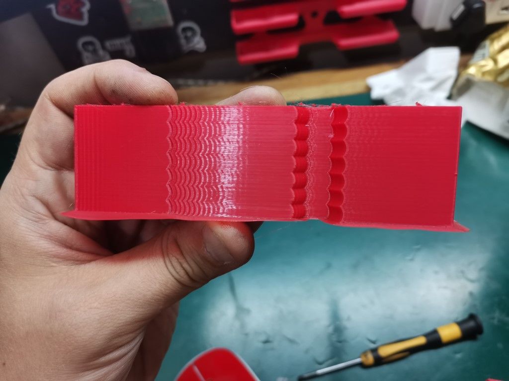
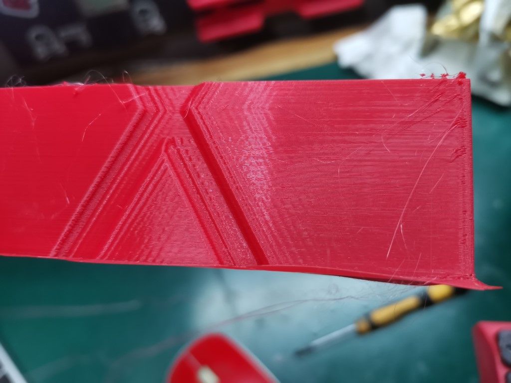
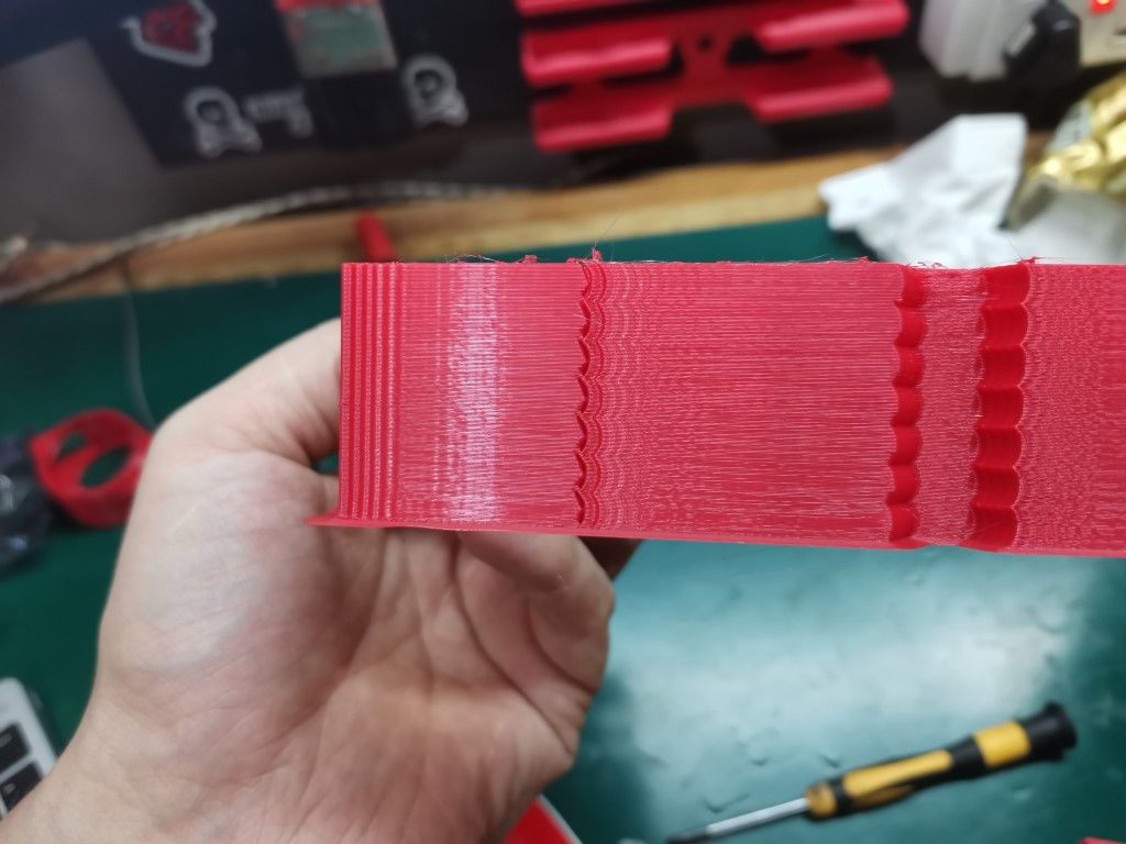
I can't spot the layer at which I turned the input shaping on, or back off, and this for any of the input shapers I tried (tried them all each one after the other). Every layer look pretty much exactly the same to me.
That's puzzling, I don't expect it to make miracles of course, but I was expecting at least some visible change, for better or worse.
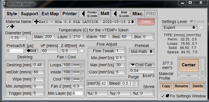
Here is what I thought was a valid setup, but as you just saw on the print pictures it didn't really make a difference:
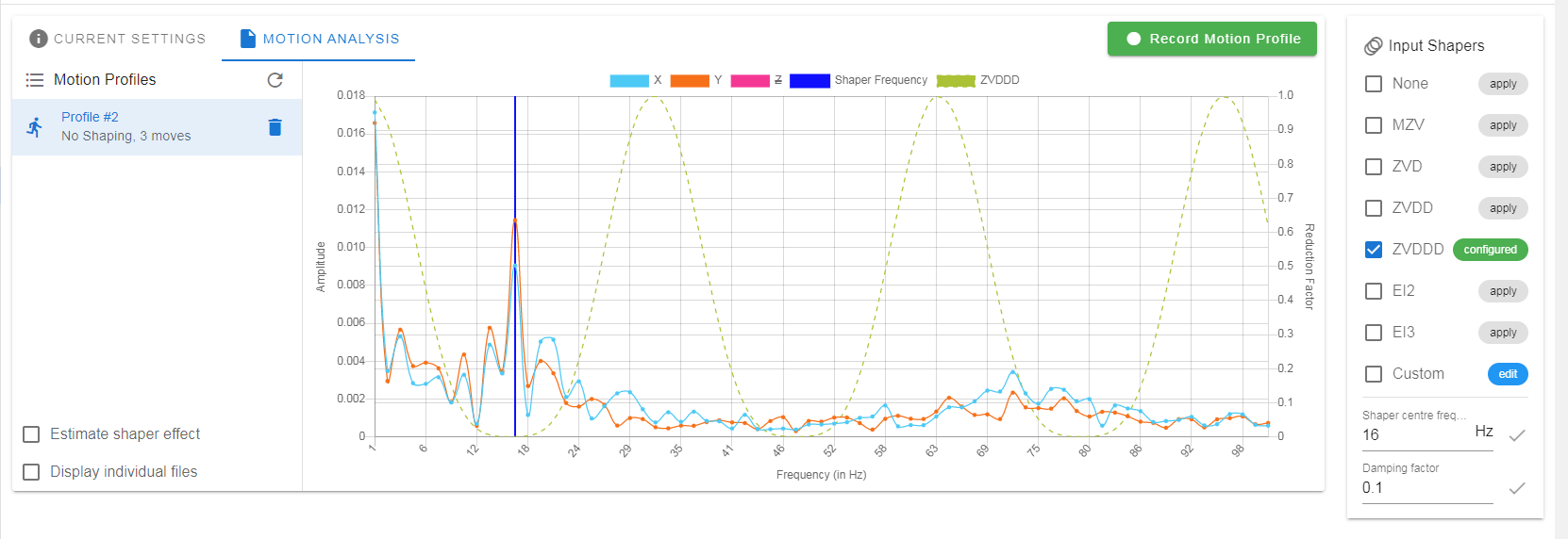
I tried different center frequencies, I tried to lower the damping to lower values, tried all the input shapers obvioulsy and also created other profiles, did many motion recordings too. I'm kinda stuck and I don't know where to look...Any idea/suggestion what could be going on there?