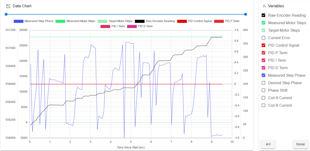
Any pointers as to where to look next? I double checked the wiring and the specs for the encoders. Everything seems to be in order.
Latest posts made by MiniFireDragon
-
RE: 1HCL Closed Loop problems and a questionposted in Duet Hardware and wiring
-
RE: 1HCL Closed Loop problems and a questionposted in Duet Hardware and wiring
Not sure what I did, but I did the code
M569 P52.0 D4
M569.6 P52.0 V1
And again, I got:
Error: M569.6: Driver 52.0 basic tuning failed, the measured motion was inconsistent
Warning: Driver 52.0 warning: tuning/calibration failed
Inside the closed loop plugin


-
RE: 1HCL Closed Loop problems and a questionposted in Duet Hardware and wiring
@dc42 Got everything updated (DWC, 1HCL, 6HC) and the firmware matches across all the boards (same as when I had 3.4). However, when I put the drive into closed loop i get:
M569 P52.0 D4
M569.6 P52.0 V1
Error: M569.6: Driver is not enabled
And the drive does not respond, even if I leave the drive in D5, there is no response. If I take it out of closed loop I can move the drive no problem. Before I could home the drive in D5 mode.
I am not sure if I am missing something in the config. I have updated to what it says for v3.5
; Drives M669 K0 ; explicitly set Cartesian kinematics, even if I should not need to M569.1 P50.0 T2 C1000 S200 R100 I0 D0 ; Configure the 1HCL board at CAN address 50 with a quadrature encoder on the motor shaft that has 5 steps per motor full step. M569.1 P52.0 T2 C1000 S200 R100 I0 D0 ; Configure the 1HCL board at CAN address 52 with a quadrature encoder on the motor shaft that has 5 steps per motor full step. M569.1 P53.0 T2 C1000 S200 R100 I0 D0 ; Configure the 1HCL board at CAN address 53 with a quadrature encoder on the motor shaft that has 5 steps per motor full step. M569 P51.0 S1 ; Z Axis no closed loop M569 P50.0 D5 S1 ; Y2 Configure the motor on the 1HCL at can address 50 as being in closed-loop drive mode (D4) and not reversed (S1) M569 P52.0 D5 S0 ; X1 Configure the motor on the 1HCL at can address 52 as being in closed-loop drive mode (D4) and not reversed (S1) M569 P53.0 D5 S0 ; Y1 Configure the motor on the 1HCL at can address 53 as being in closed-loop drive mode (D4) and not reversed (S1) M584 X52.0 Y53.0:50.0 Z51.0; set X and Y drivers M917 X0 Y0 ; Set the closed loop axes to have a holding current of zero M350 X32 Y32 Z16 ; set steps/mm to 32 to make full use of the encoder resolution M92 X256.6532274 Y256.6532274 Z320; steps/mm for a pro series cnc M566 X900.00 Y900.00 Z60.00 ; set maximum instantaneous speed changes (mm/min) M203 X6000.00 Y6000.00 Z180.00 ; set maximum speeds (mm/min) M201 X500.00 Y500.00 Z20.00 ; set accelerations (mm/s^2) M906 X3000 Y3000 Z800 I30 ; set motor currents (mA) and motor idle factor in per cent M84 S30 ; Set idle timeout -
RE: 1HCL Closed Loop problems and a questionposted in Duet Hardware and wiring
@Phaedrux The light was dim on the board, so there was no firmware anymore. Plugged in usb and used Bossa to upload the firmware file in dc42's link.
v3.5 is telling me:
Error in start-up file macro line 84: Unknown pin name 'exp.heater3'So I am fixing it. Not sure if that is preventing the system from working because I get this now:
M569 P52.0 D4 - gives me a green box then I run
M569.6 P52.0 V1 and get
Error: M569.6: Driver is not enabled
As of this moment, i am looking thru the docs for the name of the laser/vfd pwm pin.
-
RE: 1HCL Closed Loop problems and a questionposted in Duet Hardware and wiring
@dc42 I downloaded the files and uploaded them via the Web panel upload. It asked if I wanted to update, and I said yes. Things went by updating, it rebooted and now nothing works. The panel duo I have connected just sits there saying Connecting and I cannot connect via the network interface.
-
RE: 1HCL Closed Loop problems and a questionposted in Duet Hardware and wiring
@dc42 I am using the 1HCL 3.4.6 firmware (I downloaded the zip file for 3.4.6 and uploaded it). When I give the gcode command to list the firmware it reports back as 3.4.6.
However, I will update and try the newer version and see if that helps.
Thanks.
-
1HCL Closed Loop problems and a questionposted in Duet Hardware and wiring
I am using 4 1HCL boards to drive Nema34 with encoder stepper motors. Everything works and moves fine when in Open Loop mode and Assisted Closed Loop mode (D5). When I change it over to closed loops (D4) and run the calibration command
M569.6 P52.0 V1I get this error:
Warning: Driver 52.0 warning: tuning failed
Warning: M569.6: Driver 52.0 new tuning error(s): The measured motion was inconsistent.
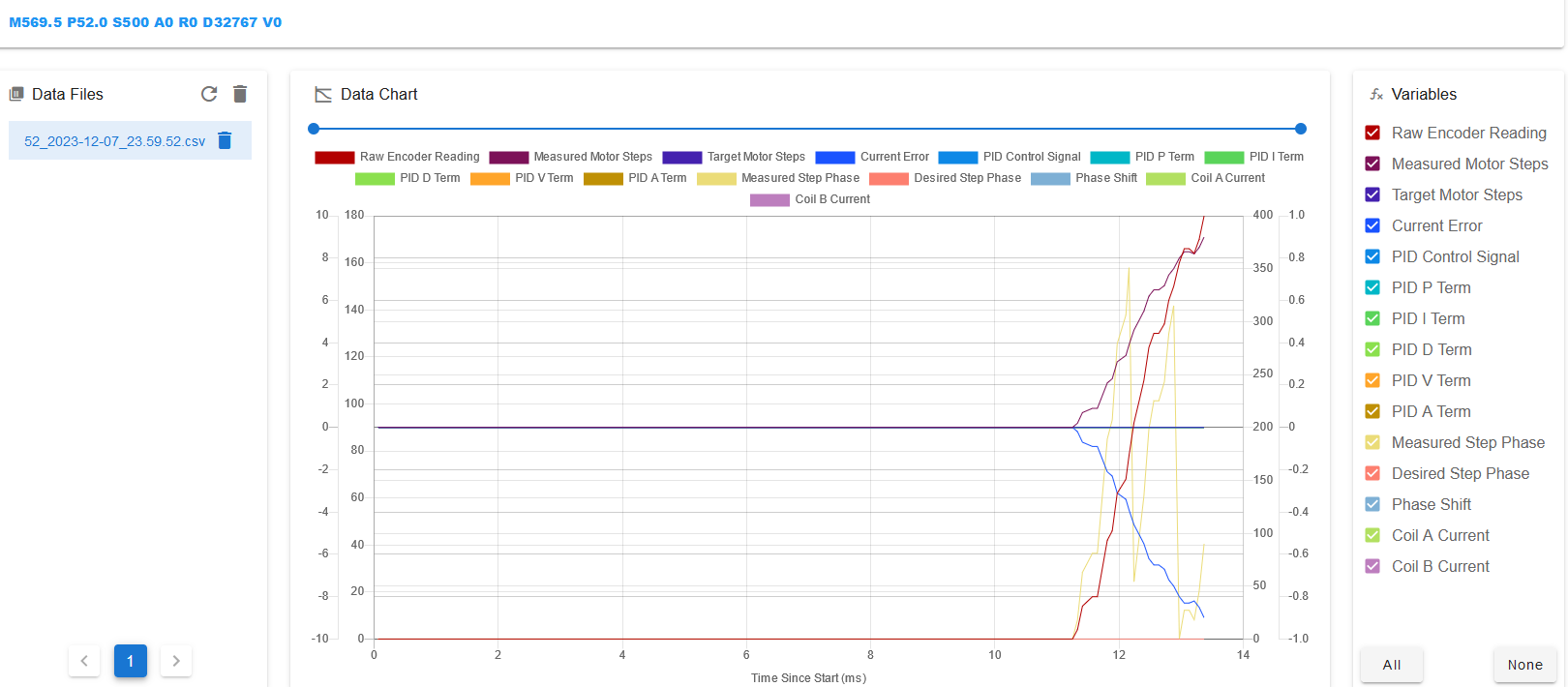
I have installed the closed loop plugin driver, but no matter what option I do, all it gives me is a scrolling blue bar after I hit record. By chance, I managed to get some kind of output from it by moving the Axis in question. Here is a screen shot of the graph:

It seems like I am getting something, but I have 0 experience knowing what I should be seeing.
Here is the driver configuration, the one I am working on is P52 atm:
; Drives
M669 K0                                         ; explicitly set Cartesian kinematics, even if I should not need to
M569.1 P50.0 T2 C5 R100 I0 D0 ; Configure the 1HCL board at CAN address 50 with a quadrature encoder on the motor shaft that has 5 steps per motor full step.
M569.1 P52.0 T2 C5 R100 I0 D0 ; Configure the 1HCL board at CAN address 52 with a quadrature encoder on the motor shaft that has 5 steps per motor full step.
M569.1 P53.0 T2 C5 R100 I0 D0  ; Configure the 1HCL board at CAN address 53 with a quadrature encoder on the motor shaft that has 5 steps per motor full step.
M569 P51.0 S1  ; Z Axis no closed loop
M569 P50.0 D5 S1 ; Y2 Configure the motor on the 1HCL at can address 50 as being in closed-loop drive mode (D4) and not reversed (S1)
M569 P52.0 D5 S0 ; X1 Configure the motor on the 1HCL at can address 52 as being in closed-loop drive mode (D4) and not reversed (S1)
M569 P53.0 D5 S0 ; Y1 Configure the motor on the 1HCL at can address 53 as being in closed-loop drive mode (D4) and not reversed (S1)
M584 X52.0 Y53.0:50.0 Z51.0; set X and Y drivers
M917 X0 Y0 ; Set the closed loop axes to have a holding current of zero
M350 X32 Y32 Z16 ; set steps/mm to 32 to make full use of the encoder resolution
M92 X256.6532274 Y256.6532274 Z320; steps/mm for a pro series cnc

M566 X900.00 Y900.00 Z60.00         ; set maximum instantaneous speed changes (mm/min)
M203 X6000.00 Y6000.00 Z180.00      ; set maximum speeds (mm/min)
M201 X500.00 Y500.00 Z20.00          ; set accelerations (mm/s^2)
M906 X3000 Y3000 Z800 I30                 ; set motor currents (mA) and motor idle factor in per cent
M84 S30                                      ; Set idle timeout
and the question:
The docs say:Duet firmware currently only supports tuning one driver at a time. This means that when tuning a multi-driver axis, one driver will move and the other(s) will not. If attempting to tune a multi-driver axis, please take appropriate mitigation to ensure the axis doesn't become stressed/misaligned when only one one driver moves.Does this mean it will do 1 driver and then the other and how does this apply to PID tuning?
Board: Duet 3 MB6HC (MB6HC)
Firmware: RepRapFirmware for Duet 3 MB6HC 3.4.6 (2023-07-21) (Web UI is same) -
RE: 3xY Axis Endstops only low or high works, not bothposted in Duet Hardware and wiring
@droftarts Thanks, this maybe useful.
-
RE: 3xY Axis Endstops only low or high works, not bothposted in Duet Hardware and wiring
@fcwilt Thanks for the information.
-
3xY Axis Endstops only low or high works, not bothposted in Duet Hardware and wiring
I am in the stage of setting up a 9'x12' CNC machine. I have a 5 pepperl+fuchs sensors on the machine. I am trying to setup my y-axis to have 2 high endstops (used for squaring the gantry) and 1 low endstop to determine the length of the bed (that way I can move the end stop and not have to reprogram the gcode).
When I have all the y endstops active, it will only tell me when the low endstop is triggered. If I rem out the Y1 endstop (as shown in the code below) and send M119, it will tell me the high endstops are triggered (as it should).
TLDR; Everything works independently, but if I add in the Y1 endstop, the system does not send a message when the Y2 are triggered.
Board: Duet 3 MB6HC (MB6HC)
Firmware: RepRapFirmware for Duet 3 MB6HC 3.4.6 (2023-07-21) (Web UI is same)GCode:
; Endstops
M574 X1 S1 P"!io4.in"                         ; configure switch-type (e.g. microswitch) endstop for low end on X via pin io1.in
M574 Y2 S1 P"!io5.in+!io1.in"                 ; configure switch-type (e.g. microswitch) endstop for low end on Y via pin io3.in
;M574 Y1 S1 P"!io2.in"                 		  ; configure switch-type (e.g. microswitch) endstop for low end on Y via pin io3.in
M574 Z2 S1 P"!io3.in"                         ; configure switch-type (e.g. microswitch) endstop for low end on Z via pin io5.in