Update:
I have found, that the steel core of my belts broke, which caused the belts to lengthen substantially over the cause of a print. I have bought genuine gates belts and the problem is gone
Best posts made by Lee
-
RE: Delta prints Skewedposted in General Discussion
Latest posts made by Lee
-
RE: Input Shaping on a Deltaposted in Tuning and tweaking
@dc42 i would say the printhead is on the heavier side because it is a direct drive setup with a orbiter v2
The accelerations are currently at 9500mm/s^2 would you recommend increasing them further? -
Input Shaping on a Deltaposted in Tuning and tweaking
Hi there,
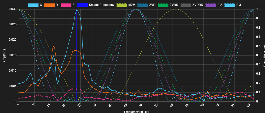
I ran a motion analysis on my delta printer using the Duet controller and need help interpreting the results. Looking for guidance on interpreting motion analysis results and any advice on fine-tuning delta printers. Any insights are greatly appreciated. Feel free to ask for more details.these are the results my results:

what would be the right frqanzy to choose here? -
RE: Delta prints Skewedposted in General Discussion
Update:
I have found, that the steel core of my belts broke, which caused the belts to lengthen substantially over the cause of a print. I have bought genuine gates belts and the problem is gone -
RE: Delta prints Skewedposted in General Discussion
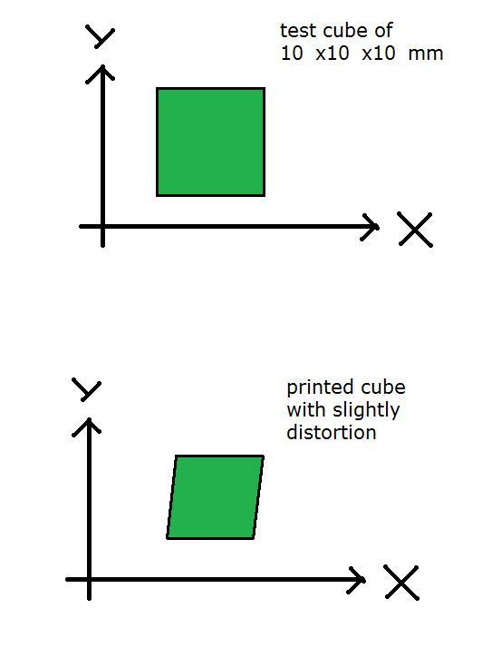
@oliof The Prints are Skewed like shown in the pic but along both axis it almost looks like skipping steps but less severe

-
Delta prints Skewedposted in General Discussion
I am currently having a problem where all my prints a skewed. I suspect It's something with the delta calibration. I have checked all my belts. I don't know what to do to fix the issue. Does anyone know what the problem could be?
Config.g
; Configuration file for Duet Maestro (firmware version 3.3)
; executed by the firmware on start-up
;
; generated by RepRapFirmware Configuration Tool v3.3.15 on Sun Mar 12 2023 20:43:39 GMT+0100 (Mitteleuropäische Normalzeit)

; General preferences
G90                                                    ; send absolute coordinates...
M83                                                    ; ...but relative extruder moves
M550 P"Kossel XL"                                      ; set printer name
M665 L371.000:371.000:371.000 R168.486 H346.526 B117.5 ; Set delta radius, diagonal rod length, printable radius and homed height B116
M666 X0 Y0 Z0                                          ; put your endstop adjustments here, or let auto calibration find them

; Network
M552 P0.0.0.0 S1                                       ; enable network and acquire dynamic address via DHCP
M586 P0 S1                                             ; enable HTTP
M586 P1 S1                                             ; enable FTP
M586 P2 S1                                             ; enable Telnet

; Drives
M569 P0 S1                                             ; physical drive 0 goes forwards
M569 P1 S1                                             ; physical drive 1 goes forwards
M569 P2 S1                                             ; physical drive 2 goes forwards
M569 P3 S0 D3                                          ; physical drive 3 goes forwards
M584 X0 Y1 Z2 E3                                       ; set drive mapping
M350 X16 Y16 Z16 I1                                    ; configure microstepping with interpolation
M350 E16 I0                                            ; configure microstepping without interpolation
M92 X160 Y160 Z160 E663.00                             ; set steps per mm
M566 X300 Y300 Z300 E300.00                            ; set maximum instantaneous speed changes (mm/min)
M203 X30000 Y30000 Z30000 E7200.00                     ; set maximum speeds (mm/min)
M201 X10000 Y10000 Z1750 E3000                         ; set accelerations (mm/s^2)
M906 X1100 Y1100 Z1100 I25                             ; set motor currents (mA) and motor idle factor in per cent
M906 E1000                                             ;I10                                         ; set motor currents (mA) and motor idle factor in per cent
M84 S25                                                ; Set idle timeout
M950 S0 C"servo"                                       ; configure servo

; Axis Limits
M208 Z0 S1                                             ; set minimum Z

; Endstops
M574 X2 S1 P"!^xstop"                                  ; configure switch-type (e.g. microswitch) endstop for high end on X via pin !^xstop
M574 Y2 S1 P"!^ystop"                                  ; configure switch-type (e.g. microswitch) endstop for high end on Y via pin !^ystop
M574 Z2 S1 P"!^zstop"                                  ; configure switch-type (e.g. microswitch) endstop for high end on Z via pin !^zstop

; Z-Probe
M558 P8 C"zprobe.in" H2 F60 T3000 R1                   ;S0.01 A15	        ; set Z probe type to effector and the dive height + speeds M558 P5 R0.4 C"zprobe.in" H2.5 F240 T1500 M558 P5 R0.75 C"zprobe.in" H5 F60 T4800
;M558 H30                                               ;*** Remove this line after delta calibration has been done and new delta parameters have been saved
G31 P1 X0 Y0 Z-0.2                                     ; set Z probe trigger value, offset and trigger height
M557 R110 S30                                          ; define mesh grid

; Heaters
M308 S0 P"bedtemp" Y"thermistor" T100000 B4092         ; configure sensor 0 as thermistor on pin bedtemp
M950 H0 C"bedheat" T0                                  ; create bed heater output on bedheat and map it to sensor 0
M307 H0 B0 S1.00                                       ; disable bang-bang mode for the bed heater and set PWM limit
M140 H0                                                ; map heated bed to heater 0
M143 H0 S100                                           ; set temperature limit for heater 0 to 100C
M308 S1 P"e0temp" Y"thermistor" T100000 B4725 C7.06e-8 ; configure sensor 1 as thermistor on pin e0temp
M950 H1 C"e0heat" T1                                   ; create nozzle heater output on e0heat and map it to sensor 1
M307 H1 B0 S1.00                                       ; disable bang-bang mode for heater  and set PWM limit
M143 H1 S280                                           ; set temperature limit for heater 1 to 280C

; Fans
M950 F0 C"fan0" Q500                                   ; create fan 0 on pin fan0 and set its frequency
M106 P0 C"Part cooling Fan" S0 H-1                     ; set fan 0 name and value. Thermostatic control is turned off
M950 F1 C"fan1" Q500                                   ; create fan 1 on pin fan1 and set its frequency
M106 P1 C"Hotend Fan" S1 H1 T45                        ; set fan 1 name and value. Thermostatic control is turned on

; Tools
M563 P0 S"E3D V6" D0 H1 F0                             ; define tool 0
G10 P0 X0 Y0 Z0                                        ; set tool 0 axis offsets
G10 P0 R0 S0                                           ; set initial tool 0 active and standby temperatures to 0C

; Custom settings
M81 C"pson"                                            ; PSU off
;M955 P0 C"twd0+twck0" I16 R10                           ; Accelorometer
M107                                                   ; fans off

M572 D0 S0.08                                          ; Set Pressure advance
M579 X0.994 Y0.989 Z1                                  ; Scale Cartesian axes


; Input shaping
M593 P"zvd" F34.937696796618701422547321865658 S0


;Orbiter Filament Sensor
;Triggers

M950 J2 C"!e0_stop"                                    ; define logical input for filament auto load
M581 P2 T3 S0 R0                                       ; define trigger for filament auto load triggers trigger3.g

M950 J3 C"!exp.pa21"                                   ; define logical input for filament unload
M581 P3 T4 S0 R0                                       ; define trigger for filament auto un load triggers trigger4.g

M591 D0 P2 C"!^e1_stop" S1                             ; filament monitor connected to E1_stop


; Miscellaneous
M501                                                   ; load saved parameters from non-volatile memory
T0                                                     ; select first tool
config-override.g:
; config-override.g file generated in response to M500 at 2023-07-07 22:33
; This is a system-generated file - do not edit
; Delta parameters
M665 L371.000:371.000:371.000 R166.722 H345.973 B117.5 X-0.093 Y-0.009 Z0.000
M666 X0.030 Y0.082 Z-0.113 A0.00 B0.00
; Heater model parameters
M307 H0 R0.426 K0.733:0.000 D2.00 E1.35 S1.00 B0
M307 H1 R1.705 K0.266:0.071 D5.66 E1.35 S1.00 B0 V24.0
; Workplace coordinates
G10 L2 P1 X0.00 Y0.00 Z0.00
G10 L2 P2 X0.00 Y0.00 Z0.00
G10 L2 P3 X0.00 Y0.00 Z0.00
G10 L2 P4 X0.00 Y0.00 Z0.00
G10 L2 P5 X0.00 Y0.00 Z0.00
G10 L2 P6 X0.00 Y0.00 Z0.00
G10 L2 P7 X0.00 Y0.00 Z0.00
G10 L2 P8 X0.00 Y0.00 Z0.00
G10 L2 P9 X0.00 Y0.00 Z0.00
Bed.g
; bed.g ; called to perform automatic delta calibration via G32 ; ; generated by RepRapFirmware Configuration Tool v3.3.16 on Tue Mar 21 2023 17:36:46 GMT+0100 (Mitteleuropäische Normalzeit) M561 ; clear any bed transform G28 ; home all towers M280 P0 S50 ; Move servo to 50° M201 X200 Y200 Z200 E3000 M906 X500 Y500 Z500 M564 S0 ;G30 P0 X0 Y0 Z-99999 G4 S1 ; Wait 1 Sek ; Probe the bed at 12 peripheral and 3 halfway points, and perform 6-factor auto compensation ; Before running this, you should have set up your Z-probe trigger height to suit your build, in the G31 command in config.g. G30 P0 X0 Y119.9 H0 Z-99999 G30 P1 X59.95 Y103.84 H0 Z-99999 G30 P2 X103.84 Y59.95 H0 Z-99999 G30 P3 X119.9 Y0 H0 Z-99999 G30 P4 X103.84 Y-59.95 H0 Z-99999 G30 P5 X59.95 Y-103.84 H0 Z-99999 G30 P6 X0 Y-119.9 H0 Z-99999 G30 P7 X-59.95 Y-103.84 H0 Z-99999 G30 P8 X-103.84 Y-59.95 H0 Z-99999 G30 P9 X-119.9 Y0 H0 Z-99999 G30 P10 X-103.84 Y59.95 H0 Z-99999 G30 P11 X-59.95 Y103.84 H0 Z-99999 G30 P12 X0 Y59.9 H0 Z-99999 G30 P13 X51.88 Y-29.95 H0 Z-99999 G30 P14 X-51.88 Y-29.95 H0 Z-99999 G30 P15 X0 Y0 H0 Z-99999 S6 ; Use S-1 for measurements only, without calculations. Use S4 for endstop heights and Z-height only. Use S6 for full 6 factors ; If your Z probe has significantly different trigger heights depending on XY position, adjust the H parameters in the G30 commands accordingly. The value of each H parameter should be (trigger height at that XY position) - (trigger height at centre of bed) M564 S1 -
RE: Problems with input shapingposted in Tuning and tweaking
@tas Thanks for the tip, I will definitely try that. I just finished running a test which looks promising. What I ended up doing was taking an average of the frequencies I calculated and used that as my shaper frequency and I think it looks good.
This was Printed at 100 mm/s.

-
RE: Problems with input shapingposted in Tuning and tweaking
@tas I will check all the bolts again and tighten my belts up even more again and try to run something other than the ringing test, but thanks for your help anyway.
-
RE: Problems with input shapingposted in Tuning and tweaking
@gloomyandy I am now confused as heck. I have tried the manual tuning around 15 times and none of my test were consistent, and the last one was the one that confused me the most. I had both input shaping and pressure advanced off. And it had next to no ringing. But the test before that with the exact same settings and gcode had a hell of a lot of ringing. WTF is going on?
And the frequencies I calculated are all around 34 Hz and from what I heard here that seems to low
I am running a direct drive extruder, which makes the tool head heavier but dose more weight lead to lower frequency?
-
RE: Problems with input shapingposted in Tuning and tweaking
@gloomyandy I think manually turning it may be my best option becasue i dont think it a mounting issue
-
RE: Problems with input shapingposted in Tuning and tweaking
@jay_s_uk ok than i will design a new holder