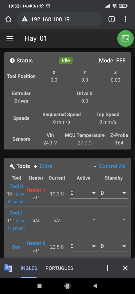
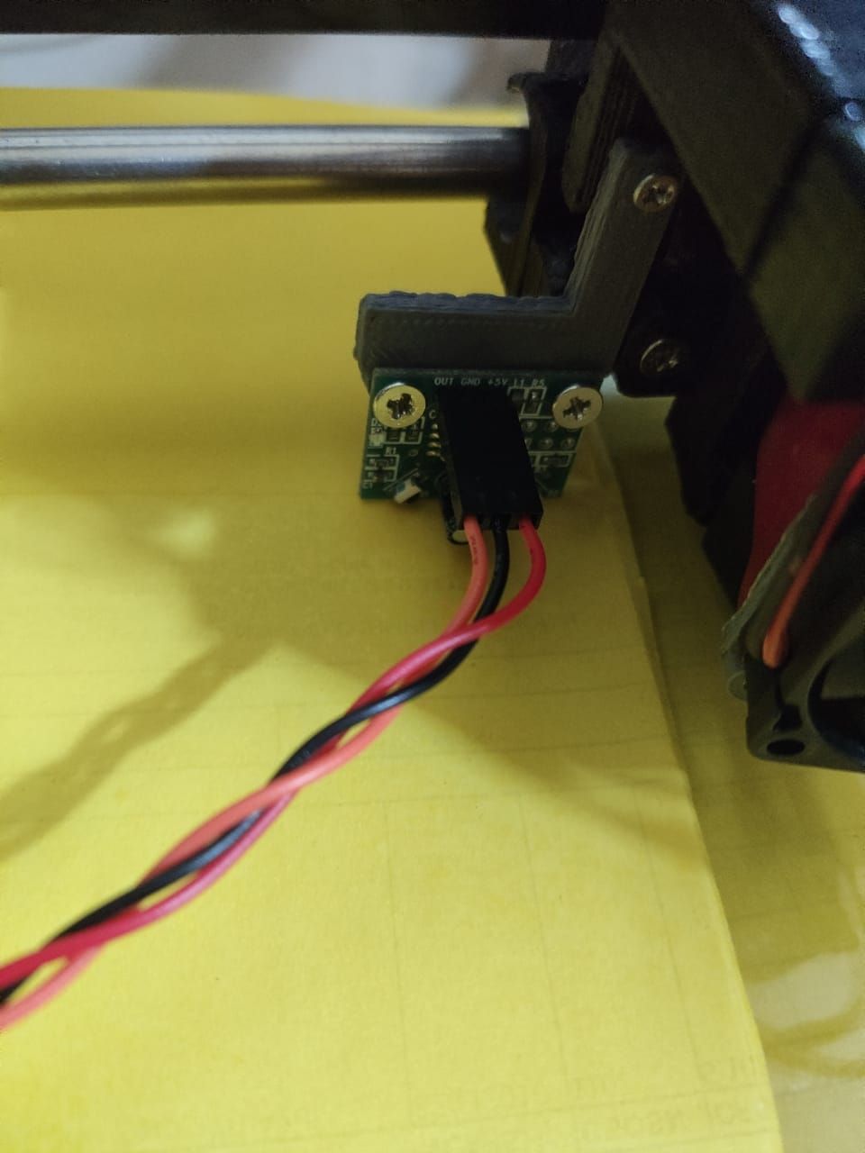
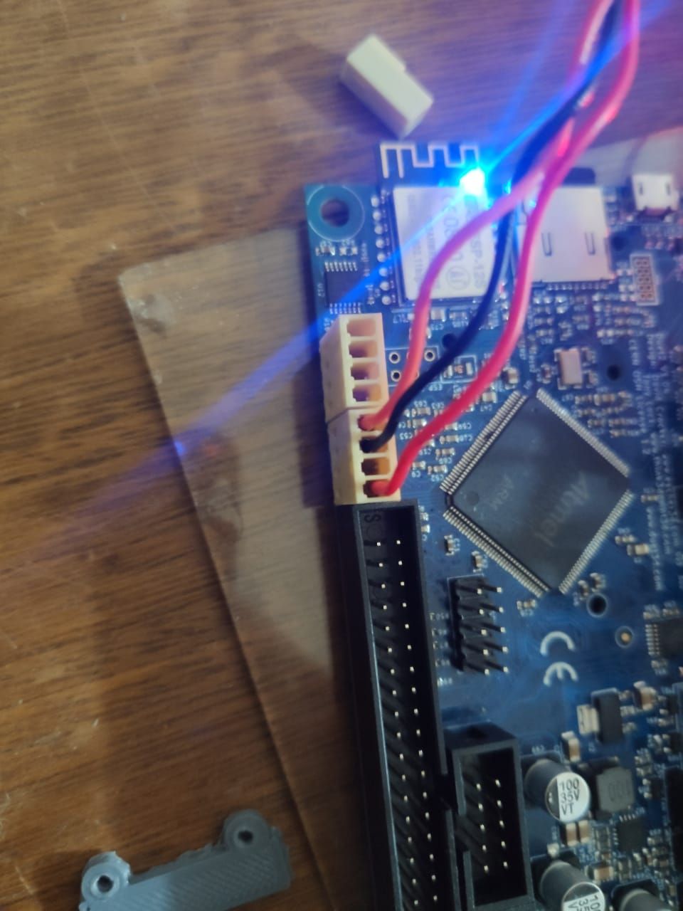
@whopping-pochard yes ... on my web duet is showing this

Posts made by herlander
-
RE: IR-Prome not workingposted in Duet Hardware and wiring
-
IR-Prome not workingposted in Duet Hardware and wiring
Today I went to install my IR-probe, however it doesn't work ... I've tried everything I validated more than 50 times the pinout and it should work, or at least give a sign of life ...
Board: Duet 2 WiFi (2WiFi)
Firmware: RepRapFirmware for Duet 2 WiFi/Ethernet 3.1.1 (2020-05-19b2)
Duet WiFi Server Version: 1.23bed.g
; bed.g
; called to perform automatic bed compensation via G32
;
; generated by RepRapFirmware Configuration Tool v3.1.4 on Sat Sep 12 2020 13:13:28 GMT-0300 (Brasilia Standard Time)
;G28 ; home
;M401 ; deploy Z probe (omit if using bltouch)
;G30 P0 X20 Y100 Z-99999 ; probe near a leadscrew, half way along Y axis
;G30 P1 X180 Y100 Z-99999 S2 ; probe near a leadscrew and calibrate 2 motors
;M402 ; retract probe (omit if using bltouch)
M561 ; clear any bed transform
G28 ; home all axis
G29  ; probe the bed and enable compensation
config.g
; Drives
M569 P0 S1                                         ; physical drive 0 goes forwards
M569 P1 S1                                         ; physical drive 1 goes forwards
M569 P2 S0                                         ; physical drive 2 goes backwards
M569 P3 S0                                         ; physical drive 3 goes backwards
M569 P4 S0                                         ; physical drive 4 goes backwards

M584 X0 Y1 Z2:4 E3                                   ; set drive mapping

M350 X16 Y16 Z16 E16 I1                            ; configure microstepping with interpolation
M92 X80.00 Y80.00 Z1600.00 E495.35                  ; set steps per mm
M566 X900.00 Y900.00 Z12.00 E120.00                ; set maximum instantaneous speed changes (mm/min)
M203 X18000.00 Y18000.00 Z180.00 E1500.00          ; set maximum speeds (mm/min)
M201 X3000.00 Y3000.00 Z100.00 E10000.00           ; set accelerations (mm/s^2)
M906 X800 Y800 Z800 E800 I30                       ; set motor currents (mA) and motor idle factor in per cent

;M92 X80.00 Y80.00 Z1600 E785.60                  ; set steps per mm
;M566 X900.00 Y900.00 Z12.00 E120.00                 ; set maximum instantaneous speed changes (mm/min)
;M203 X6000.00 Y6000.00 Z180.00 E1200.00             ; set maximum speeds (mm/min)
;M201 X500.00 Y500.00 Z20.00 E250.00                 ; set accelerations (mm/s^2)
;M906 X800 Y800 Z800 E800 I30                       ; set motor currents (mA) and motor idle factor in per cent
M84 S30                                            ; Set idle timeout

; Axis Limits
M208 X0 Y0 Z0 S1                                   ; set axis minima
M208 X300 Y330 Z200 S0                             ; set axis maxima

; Endstops
M574 X1 S1 P"xstop"                                ; configure active-high endstop for low end on X via pin xstop
M574 Y1 S1 P"ystop"                                ; configure active-high endstop for low end on Y via pin ystop
M574 Z1 S1 P"zstop+e1stop"                                ; configure active-high endstop for low end on Z via pin zstop

; Z-Probe
;M558 P1 C"zprobe.in" H5 F120 T6000                                                              ; Set endstops controlled by probe
M558 P1 C"zprobe.in" H5 F120 T6000             ; set Z probe type to unmodulated and the dive height + speeds
G31 P500 X0 Y0 Z2.5                            ; set Z probe trigger value, offset and trigger height
M557 X35:265 Y35:265 P2                                                 ; Define mesh grid (for glass bed 4 points are more than enough)


; Heaters
M308 S0 P"bedtemp" Y"thermistor" T100000 B4138 ; configure sensor 0 as thermistor on pin bedtemp
M950 H0 C"bedheat" T0                          ; create bed heater output on bedheat and map it to sensor 0
M307 H0 A108.4 C588.7 D0.4 S1.00 V22 B0      ; disable bang-bang mode for the bed heater and set PWM limit
M140 H0                                        ; map heated bed to heater 0
M143 H0 S120                                   ; set temperature limit for heater 0 to 120C
M308 S1 P"e0temp" Y"thermistor" T100000 B4138  ; configure sensor 1 as thermistor on pin e0temp
M950 H1 C"e0heat" T1                           ; create nozzle heater output on e0heat and map it to sensor 1
M308 S2 P"drivers" Y"drivers" A"DRIVERS"  ; configure sensor 2 as temperature warning and overheat flags on the TMC2660 on Duet
M308 S3 P"mcu-temp" Y"mcu-temp" A"Duet Board" ; Configure MCU sensor


; Fans
M950 F0 C"fan0" Q500                           ; create fan 0 on pin fan0 and set its frequency
M106 P0 C"Part Fan" S0 H-1                     ; set fan 0 name and value. Thermostatic control is turned off
M950 F1 C"fan1" Q500                           ; create fan 1 on pin fan1 and set its frequency
M106 P1 C"Hotend Fan" S1 H1 T40                ; set fan 1 name and value. Thermostatic control is turned on
M950 F2 C"fan2" Q500 ; Define Fan_2 for use - Duet board cooling - PWM fan
M106 P2 H2:3 T15:70 C"Duet Fan" ; Set fan 2. Manages Duet board fan.


; Tools
M563 P0 D0 H1 F0                               ; define tool 0
G10 P0 X0 Y0 Z0                                ; set tool 0 axis offsets
G10 P0 R0 S0                                   ; set initial tool 0 active and standby temperatures to 0C
M563 P1 D0 F-1                                 ; define tool 2
G10 P1 X0 Y0 Z0                                ; set tool 2 axis offsets
G10 P1 R0 S0                                   ; set initial tool 2 active and standby temperatures to 0C


; Custom settings are not defined

; Miscellaneous
M911 S10 R11 P"M913 X0 Y0 G91 M83 G1 Z3 E-5 F1000" ; set voltage thresholds and actions to run on power loss
